Qualification de IONIC, instrument de recombinaison ...
Qualification de IONIC, instrument de recombinaison ...
Qualification de IONIC, instrument de recombinaison ...
You also want an ePaper? Increase the reach of your titles
YUMPU automatically turns print PDFs into web optimized ePapers that Google loves.
tel-00010396, version 1 - 4 Oct 2005<br />
TABLE DES FIGURES vii<br />
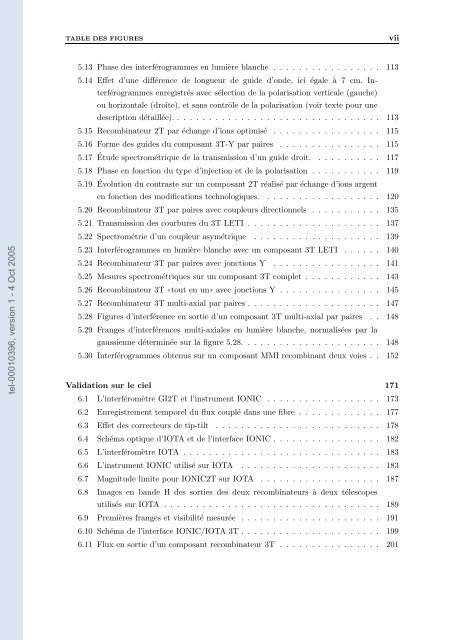
5.13 Phase <strong>de</strong>s interférogrammes en lumière blanche . . . . . . . . . . . . . . . . . 113<br />
5.14 Effet d’une différence <strong>de</strong> longueur <strong>de</strong> gui<strong>de</strong> d’on<strong>de</strong>, ici égale à 7 cm. In-<br />
terférogrammes enregistrés avec sélection <strong>de</strong> la polarisation verticale (gauche)<br />
ou horizontale (droite), et sans contrôle <strong>de</strong> la polarisation (voir texte pour une<br />
<strong>de</strong>scription détaillée). . . . . . . . . . . . . . . . . . . . . . . . . . . . . . . . . 113<br />
5.15 Recombinateur 2T par échange d’ions optimisé . . . . . . . . . . . . . . . . . 115<br />
5.16 Forme <strong>de</strong>s gui<strong>de</strong>s du composant 3T-Y par paires . . . . . . . . . . . . . . . . 115<br />
5.17<br />
Étu<strong>de</strong> spectrométrique <strong>de</strong> la transmission d’un gui<strong>de</strong> droit. . . . . . . . . . . 117<br />
5.18 Phase en fonction du type d’injection et <strong>de</strong> la polarisation . . . . . . . . . . . 119<br />
5.19 Évolution du contraste sur un composant 2T réalisé par échange d’ions argent<br />
en fonction <strong>de</strong>s modifications technologiques. . . . . . . . . . . . . . . . . . . 120<br />
5.20 Recombinateur 3T par paires avec coupleurs directionnels . . . . . . . . . . . 135<br />
5.21 Transmission <strong>de</strong>s courbures du 3T LETI . . . . . . . . . . . . . . . . . . . . . 137<br />
5.22 Spectrométrie d’un coupleur asymétrique . . . . . . . . . . . . . . . . . . . . 139<br />
5.23 Interférogrammes en lumière blanche avec un composant 3T LETI . . . . . . 140<br />
5.24 Recombinateur 3T par paires avec jonctions Y . . . . . . . . . . . . . . . . . 141<br />
5.25 Mesures spectrométriques sur un composant 3T complet . . . . . . . . . . . . 143<br />
5.26 Recombinateur 3T ✭tout en un ✮ avec jonctions Y . . . . . . . . . . . . . . . . 145<br />
5.27 Recombinateur 3T multi-axial par paires . . . . . . . . . . . . . . . . . . . . . 147<br />
5.28 Figures d’interférence en sortie d’un composant 3T multi-axial par paires . . 148<br />
5.29 Franges d’interférences multi-axiales en lumière blanche, normalisées par la<br />
gaussienne déterminée sur la figure 5.28. . . . . . . . . . . . . . . . . . . . . . 148<br />
5.30 Interférogrammes obtenus sur un composant MMI recombinant <strong>de</strong>ux voies . . 152<br />
Validation sur le ciel 171<br />
6.1 L’interféromètre GI2T et l’<strong>instrument</strong> <strong>IONIC</strong> . . . . . . . . . . . . . . . . . . 173<br />
6.2 Enregistrement temporel du flux couplé dans une fibre . . . . . . . . . . . . . 177<br />
6.3 Effet <strong>de</strong>s correcteurs <strong>de</strong> tip-tilt . . . . . . . . . . . . . . . . . . . . . . . . . . 178<br />
6.4 Schéma optique d’IOTA et <strong>de</strong> l’interface <strong>IONIC</strong> . . . . . . . . . . . . . . . . . 182<br />
6.5 L’interféromètre IOTA . . . . . . . . . . . . . . . . . . . . . . . . . . . . . . . 183<br />
6.6 L’<strong>instrument</strong> <strong>IONIC</strong> utilisé sur IOTA . . . . . . . . . . . . . . . . . . . . . . 183<br />
6.7 Magnitu<strong>de</strong> limite pour <strong>IONIC</strong>2T sur IOTA . . . . . . . . . . . . . . . . . . . 187<br />
6.8 Images en ban<strong>de</strong> H <strong>de</strong>s sorties <strong>de</strong>s <strong>de</strong>ux recombinateurs à <strong>de</strong>ux télescopes<br />
utilisés sur IOTA . . . . . . . . . . . . . . . . . . . . . . . . . . . . . . . . . . 189<br />
6.9 Premières franges et visibilité mesurée . . . . . . . . . . . . . . . . . . . . . . 191<br />
6.10 Schéma <strong>de</strong> l’interface <strong>IONIC</strong>/IOTA 3T . . . . . . . . . . . . . . . . . . . . . . 199<br />
6.11 Flux en sortie d’un composant recombinateur 3T . . . . . . . . . . . . . . . . 201


