

Preliminary C8051F120/1/2/3 C8051F124/5/6/7 - KEMT FEI TUKE
Preliminary C8051F120/1/2/3 C8051F124/5/6/7 - KEMT FEI TUKE
Preliminary C8051F120/1/2/3 C8051F124/5/6/7 - KEMT FEI TUKE

Create successful ePaper yourself
Turn your PDF publications into a flip-book with our unique Google optimized e-Paper software.
<strong>Preliminary</strong><br />
<strong>C8051F120</strong>/1/2/3<br />
<strong>C8051F124</strong>/5/6/7<br />
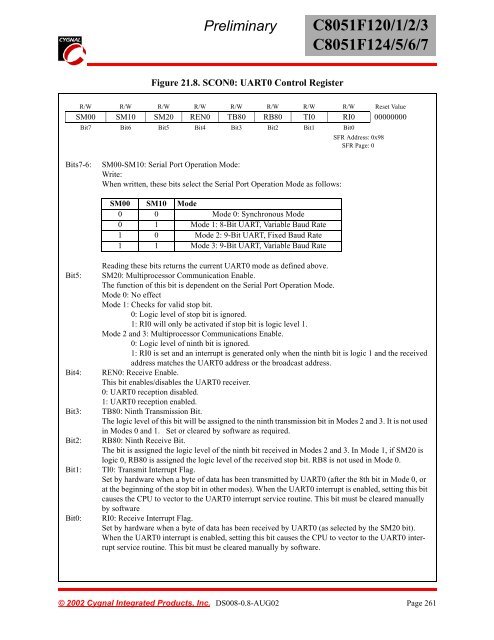
Figure 21.8. SCON0: UART0 Control Register<br />
R/W R/W R/W R/W R/W R/W R/W R/W Reset Value<br />
SM00 SM10 SM20 REN0 TB80 RB80 TI0 RI0 00000000<br />
Bit7 Bit6 Bit5 Bit4 Bit3 Bit2 Bit1 Bit0<br />
SFR Address: 0x98<br />
SFR Page: 0<br />
Bits7-6:<br />
SM00-SM10: Serial Port Operation Mode:<br />
Write:<br />
When written, these bits select the Serial Port Operation Mode as follows:<br />
SM00 SM10 Mode<br />
0 0 Mode 0: Synchronous Mode<br />
0 1 Mode 1: 8-Bit UART, Variable Baud Rate<br />
1 0 Mode 2: 9-Bit UART, Fixed Baud Rate<br />
1 1 Mode 3: 9-Bit UART, Variable Baud Rate<br />
Bit5:<br />
Bit4:<br />
Bit3:<br />
Bit2:<br />
Bit1:<br />
Bit0:<br />
Reading these bits returns the current UART0 mode as defined above.<br />
SM20: Multiprocessor Communication Enable.<br />
The function of this bit is dependent on the Serial Port Operation Mode.<br />
Mode 0: No effect<br />
Mode 1: Checks for valid stop bit.<br />
0: Logic level of stop bit is ignored.<br />
1: RI0 will only be activated if stop bit is logic level 1.<br />
Mode 2 and 3: Multiprocessor Communications Enable.<br />
0: Logic level of ninth bit is ignored.<br />
1: RI0 is set and an interrupt is generated only when the ninth bit is logic 1 and the received<br />
address matches the UART0 address or the broadcast address.<br />
REN0: Receive Enable.<br />
This bit enables/disables the UART0 receiver.<br />
0: UART0 reception disabled.<br />
1: UART0 reception enabled.<br />
TB80: Ninth Transmission Bit.<br />
The logic level of this bit will be assigned to the ninth transmission bit in Modes 2 and 3. It is not used<br />
in Modes 0 and 1. Set or cleared by software as required.<br />
RB80: Ninth Receive Bit.<br />
The bit is assigned the logic level of the ninth bit received in Modes 2 and 3. In Mode 1, if SM20 is<br />
logic 0, RB80 is assigned the logic level of the received stop bit. RB8 is not used in Mode 0.<br />
TI0: Transmit Interrupt Flag.<br />
Set by hardware when a byte of data has been transmitted by UART0 (after the 8th bit in Mode 0, or<br />
at the beginning of the stop bit in other modes). When the UART0 interrupt is enabled, setting this bit<br />
causes the CPU to vector to the UART0 interrupt service routine. This bit must be cleared manually<br />
by software<br />
RI0: Receive Interrupt Flag.<br />
Set by hardware when a byte of data has been received by UART0 (as selected by the SM20 bit).<br />
When the UART0 interrupt is enabled, setting this bit causes the CPU to vector to the UART0 interrupt<br />
service routine. This bit must be cleared manually by software.<br />
© 2002 Cygnal Integrated Products, Inc. DS008-0.8-AUG02 Page 261


