Preliminary C8051F120/1/2/3 C8051F124/5/6/7 - KEMT FEI TUKE
Preliminary C8051F120/1/2/3 C8051F124/5/6/7 - KEMT FEI TUKE
Preliminary C8051F120/1/2/3 C8051F124/5/6/7 - KEMT FEI TUKE
You also want an ePaper? Increase the reach of your titles
YUMPU automatically turns print PDFs into web optimized ePapers that Google loves.
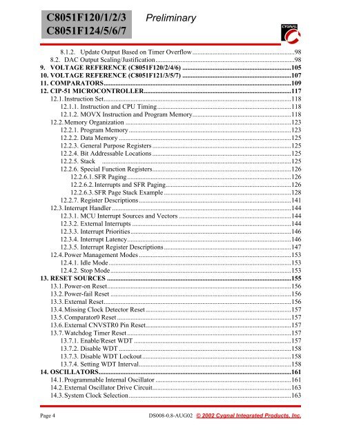
<strong>C8051F120</strong>/1/2/3<br />
<strong>C8051F124</strong>/5/6/7<br />
<strong>Preliminary</strong><br />
8.1.2. Update Output Based on Timer Overflow.............................................................98<br />
8.2. DAC Output Scaling/Justification...................................................................................98<br />
9. VOLTAGE REFERENCE (<strong>C8051F120</strong>/2/4/6) .................................................................105<br />
10. VOLTAGE REFERENCE (C8051F121/3/5/7) .................................................................107<br />
11. COMPARATORS................................................................................................................109<br />
12. CIP-51 MICROCONTROLLER........................................................................................117<br />
12.1.Instruction Set................................................................................................................118<br />
12.1.1. Instruction and CPU Timing................................................................................118<br />
12.1.2. MOVX Instruction and Program Memory...........................................................118<br />
12.2.Memory Organization ...................................................................................................123<br />
12.2.1. Program Memory.................................................................................................123<br />
12.2.2. Data Memory .......................................................................................................125<br />
12.2.3. General Purpose Registers ...................................................................................125<br />
12.2.4. Bit Addressable Locations ...................................................................................125<br />
12.2.5. Stack .................................................................................................................125<br />
12.2.6. Special Function Registers...................................................................................126<br />
12.2.6.1.SFR Paging..................................................................................................126<br />
12.2.6.2.Interrupts and SFR Paging...........................................................................126<br />
12.2.6.3.SFR Page Stack Example ............................................................................128<br />
12.2.7. Register Descriptions...........................................................................................141<br />
12.3.Interrupt Handler ...........................................................................................................144<br />
12.3.1. MCU Interrupt Sources and Vectors ...................................................................144<br />
12.3.2. External Interrupts ...............................................................................................144<br />
12.3.3. Interrupt Priorities................................................................................................146<br />
12.3.4. Interrupt Latency..................................................................................................146<br />
12.3.5. Interrupt Register Descriptions............................................................................147<br />
12.4.Power Management Modes ...........................................................................................153<br />
12.4.1. Idle Mode.............................................................................................................153<br />
12.4.2. Stop Mode............................................................................................................153<br />
13. RESET SOURCES ..............................................................................................................155<br />
13.1.Power-on Reset..............................................................................................................156<br />
13.2.Power-fail Reset ............................................................................................................156<br />
13.3.External Reset................................................................................................................156<br />
13.4.Missing Clock Detector Reset.......................................................................................157<br />
13.5.Comparator0 Reset ........................................................................................................157<br />
13.6.External CNVSTR0 Pin Reset.......................................................................................157<br />
13.7.Watchdog Timer Reset..................................................................................................157<br />
13.7.1. Enable/Reset WDT ..............................................................................................157<br />
13.7.2. Disable WDT .......................................................................................................158<br />
13.7.3. Disable WDT Lockout.........................................................................................158<br />
13.7.4. Setting WDT Interval...........................................................................................158<br />
14. OSCILLATORS...................................................................................................................161<br />
14.1.Programmable Internal Oscillator .................................................................................161<br />
14.2.External Oscillator Drive Circuit...................................................................................163<br />
14.3.System Clock Selection.................................................................................................163<br />
Page 4<br />
DS008-0.8-AUG02 © 2002 Cygnal Integrated Products, Inc.


