

Project Cyclops, A Design... - Department of Earth and Planetary ...
Project Cyclops, A Design... - Department of Earth and Planetary ...
Project Cyclops, A Design... - Department of Earth and Planetary ...

You also want an ePaper? Increase the reach of your titles
YUMPU automatically turns print PDFs into web optimized ePapers that Google loves.
<strong>and</strong>s, each covering a 1.35 to 1 frequency range are<br />
used, giving the following ranges:<br />
B<strong>and</strong> Range (GHz) Coverage (MHz)<br />
1 0.5 -0.675 175<br />
2 0.675-0.91 235<br />
3 0.91 -1.23 320<br />
4 1.23 -1.66 430<br />
5 1.66 -2.24 580<br />
6 2.24 -3.02 780<br />
The portion <strong>of</strong> the receiver associated with each b<strong>and</strong><br />
comprises a circularly symmetric feedhorn coupled to<br />
two up-converters, one for each orthogonal polarization<br />
mode. The up-converters in use are cooled to 20° K <strong>and</strong><br />
their outputs are fed to two masers operating at 10 GHz<br />
(or higher) <strong>and</strong> cooled to 4° K. The maser outputs are<br />
further amplified <strong>and</strong> then down converted to the IF<br />
frequency. Precision frequencies derived from a hydrogen<br />
maser are used for the up- <strong>and</strong> down-conversions,<br />
<strong>and</strong> the array phasing is done in the final down<br />
conversion.<br />
Two IF channels per receiver are proposed, one for<br />
each polarization. As shown in Appendix H, the choice<br />
<strong>of</strong> orthogonal polarizations is arbitrary. Thus vertical<br />
<strong>and</strong> horizontal linear, or right <strong>and</strong> left circular polarization<br />
may be used. From the two polarizations selected<br />
four additional polarizations may be resolved at the central<br />
processing station to give a total <strong>of</strong> six: V, H, V + H<br />
(or 45°), V - H (or 135°), V + /1t (left circular) <strong>and</strong><br />
V-/11 (right circular). If all six are processed the average<br />
loss, for a signal <strong>of</strong> unknown polarization, is 0.4 dB <strong>and</strong><br />
the maximum loss is 1 dB. If only four polarizations are<br />
processed the average loss is 0.7 dB <strong>and</strong> the maximum<br />
loss is 3 dB. Since 3 dB represents a loss <strong>of</strong> half the antenna<br />
surface <strong>and</strong> since processing costs are much less<br />
than antenna costs, it is recommended that all six polarizations<br />
be processed.<br />
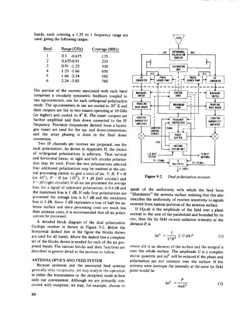
A detailed block diagram <strong>of</strong> the dual polarization<br />
<strong>Cyclops</strong> receiver is shown in Figure 9-2. Below the<br />
horizontal dashed line in the figure the blocks shown<br />
are used for all b<strong>and</strong>s. Above the dashed line a complete<br />
set <strong>of</strong> the blocks shown is needed for each <strong>of</strong> the six proposed<br />
b<strong>and</strong>s. The various blocks <strong>and</strong> their functions are<br />
described in greater detail in the sections to follow.<br />
ANTENNA OPTICS AND FEED SYSTEM<br />
Because antennas <strong>and</strong> the associated feed systems<br />
generally obey reciprocity, we may analyze the operation<br />
in either the transmission or the reception mode as best<br />
suits our convenience. Although we are primarily concerned<br />
with reception, we may, for example, choose to<br />
C,CI 0,TR0C0NAL / NHC<br />
-- t rOLAmZAT_ON [ 'l<br />
I c°uPL" / ' '<br />
t O,,Tt<br />
i uF-'-I. F-'-Cff_. I j PNASE - I J uP I<br />
1 CONVERTER _ LOCEED PUMP _'_ I _'"I LOC_D PUNP _-_ CONVERTER I<br />
U ........ L__<br />
EF£F- F?f I SWITCH I<br />
_. i I r 6ROAOEAM_ 1 " : _[ TRAVELING [<br />
I lAVE MASER _ PUMP l I " "[ lAVE MASER I<br />
' I " ' l<br />
SCHOTTI_Y I _ FREOUENCY _" SC_TTI_'<br />
BARRIERFET ' I [ _ SYNTHESIZER '' ["-I IBARRIERIrET<br />
1<br />
ANPLIFIER__JCONPUTER I. Izs.Hz / r---I-_ AII_IFIER<br />
CONTROL I I ÷ , /<br />
SIGNA'SlI I PHASE_ ,(_<br />
L.O. OlSr __._<br />
SYSTEM<br />
STATIOII UNIT /<br />
/5-IT5NHz _ MULTIPLEX IF I"<br />
I<br />
lf tABLE<br />
TS-ITSNHZ<br />
TO NEXT<br />
ANTENNA<br />
Figure 9-2. Dual polarization receiver.<br />
speak <strong>of</strong> the uniformity with which the feed horn<br />
"illuminates" the antenna surface realizing that this also<br />
describes the uniformity <strong>of</strong> receiver sensitivity to signals<br />
received from various portions <strong>of</strong> the antenna surface.<br />
If U(,o,_) is the amplitude <strong>of</strong> the field over a plane<br />
normal to the axis <strong>of</strong> the paraboloid <strong>and</strong> bounded by its<br />
rim, then the far field on-axis radiation intensity at the<br />
distance R is<br />
1<br />
lul 2 = --_2R----7 If UdAI 2 (1)<br />
where dA is an element <strong>of</strong> the surface <strong>and</strong> the integral is<br />
over the whole surface. The amplitude U is a complex<br />
vector quantity <strong>and</strong> lul 2 will be reduced if the phase <strong>and</strong><br />
polarization are not constant over the surface. If the<br />
antenna were isotropic the intensity at the same far field<br />
point would be<br />
P<br />
lul= =-- (2)<br />
4rrR 2<br />
88


