

Project Cyclops, A Design... - Department of Earth and Planetary ...
Project Cyclops, A Design... - Department of Earth and Planetary ...
Project Cyclops, A Design... - Department of Earth and Planetary ...

Create successful ePaper yourself
Turn your PDF publications into a flip-book with our unique Google optimized e-Paper software.
SHADOWED<br />
AREA<br />
SHADOWED<br />
AREA<br />
//<br />
//<br />
/<br />
/<br />
/<br />
ROT T TLE<br />
/<br />
f<br />
FOCAL<br />
POINT<br />
\<br />
/<br />
\<br />
/<br />
X<br />
\<br />
\<br />
/<br />
/<br />
/<br />
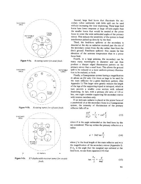
Figure 9-5a. Rotating turret for axial feeds.<br />
Figure<br />
/ - )\<br />
9-5b.<br />
"x,_<br />
'\ /<br />
FOCAL/<br />
PO, y/<br />
ROTATABLE<br />
X<br />
\<br />
\<br />
/<br />
/<br />
/<br />
TURRET<br />
Ro taring turret for <strong>of</strong>f-axis ]beds.<br />
Second, large feed horns that illuminate the secondary<br />
rather uniformly with little spill can be used<br />
without increasing the total shadowing. These large feed<br />
horns have lower response at large <strong>of</strong>f-axis angles than<br />
the smaller horns that would be needed at the prime<br />
focus to cover the wide subtended angles <strong>of</strong> the primary<br />
mirror. This reduces the sensitivity <strong>of</strong> the system to local<br />
interference picked up directly by the feed.<br />
Third, the feed-horn spillover at the secondary is<br />
directed at the sky so radiation received past the rim <strong>of</strong><br />
the secondary comes from the sky rather than from the<br />
(hot) ground. Feed-horn spillover thus causes far less<br />
elevation <strong>of</strong> the antenna temperature than in a prime<br />
focus feed.<br />
Fourth, in a large antenna, the secondary can be<br />
many many wavelengths in diameter <strong>and</strong> can thus<br />
produce a sharper edged illumination pattern on the<br />
primary mirror than a small horn. This allows the ground<br />
spill to be reduced or a more uniform primary illumination<br />
to be realized, or both.<br />
Finally, a Cassegrainian system having a magnification<br />
rn allows an f/d ratio l/m times as large to be used for<br />
the main reflector for a given feed-horn pattern. (See<br />
Appendix I.) This larger ratio greatly reduces the length<br />
<strong>of</strong> the legs <strong>of</strong> the supporting tripod or tetrapod, which in<br />
turn permits a smaller cross section with reduced<br />
shadowing. In fact, with a primary f/d ratio <strong>of</strong> 114 or<br />
less, one might consider supporting the secondary mirror<br />
with tension members only.<br />
If an isotropic radiator is placed at the prime focus <strong>of</strong><br />
a paraboloid or at the secondary focus in a Cassegrainian<br />
system, the intensity <strong>of</strong> illumination <strong>of</strong> the primary<br />
reflector falls <strong>of</strong>f as<br />
SHADOWED<br />
AREA<br />
//<br />
/<br />
/<br />
//<br />
/<br />
/ \<br />
]\<br />
i \<br />
@ I- I_ i<br />
IUI2 I o<br />
IUol _<br />
-<br />
Io<br />
- cos 4-<br />
2<br />
(13)<br />
where 0 is the angle subtended at the feed horn by the<br />
ray considered. This ray strikes the primary reflector at a<br />
radius<br />
[<br />
:\<br />
\<br />
x<br />
\<br />
I<br />
Figure 9-5c.<br />
6 )<br />
5 /<br />
MOVABLE i /<br />
TURRET /<br />
IOmeters<br />
XYdisp_ceablereceiverturretfor<br />
]Oeds.<br />
on-axis<br />
0<br />
P = 2mftan m<br />
2<br />
(14)<br />
where f is the focal length <strong>of</strong> the main reflector <strong>and</strong> m is<br />
the magnification <strong>of</strong> the secondary mirror (Appendix I).<br />
If 00 is the angle that the marginal rays subtend at the<br />
feed horn, we see from equation (14) that<br />
Oo d<br />
tan<br />
2<br />
-<br />
4mr<br />
(15)<br />
91


