

Project Cyclops, A Design... - Department of Earth and Planetary ...
Project Cyclops, A Design... - Department of Earth and Planetary ...
Project Cyclops, A Design... - Department of Earth and Planetary ...

You also want an ePaper? Increase the reach of your titles
YUMPU automatically turns print PDFs into web optimized ePapers that Google loves.
stripline. For 2 _< k _< 6, appropriate lengths <strong>of</strong> coaxial<br />
line may be used. For 7 _< k _< 14, it is probably more<br />
economical to use the acoustic surface wave delay units.<br />
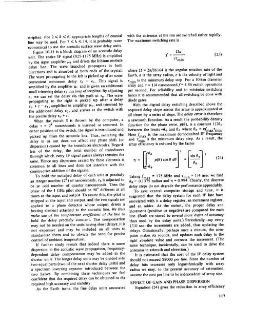
Figure I0-11 is a block diagram <strong>of</strong> an acoustic delay<br />
unit. The entire IF signal (825-1175 MHz) is amplified<br />
by the input amplifier #o <strong>and</strong> drives the lithium niobate<br />
delay line. The wave launched propagates in both<br />
directions <strong>and</strong> is absorbed at both ends <strong>of</strong> the crystal.<br />
The wave propagating to the left is picked up after some<br />
convenient minimum delay ro - el. This signal is<br />
amplified by the amplifier/zi <strong>and</strong> is given an additional<br />
small trimming delay el in a loop <strong>of</strong> stripline. By adjusting<br />
el we can set the delay via this path at Zo. The wave<br />
propagating to the right is picked up after a delay<br />
ro + r - e2, amplified in amplifier/a2, <strong>and</strong> trimmed by<br />
the additional delay e2, <strong>and</strong> arrives at the switch with<br />
the precise delay ro + r.<br />
When the switch S is thrown by the computer, a<br />
delay r = 2k nanoseconds is inserted or removed. In<br />
either position <strong>of</strong> the switch, the signal is introduced <strong>and</strong><br />
picked up from the acoustic line. Thus, switching the<br />
delay in or out does not affect any phase shift (or<br />
dispersion) caused by the transducer electrodes. Regardless<br />
<strong>of</strong> the delay, the total number <strong>of</strong> transducers<br />
through which every IF signal passes always remains the<br />
same. Hence any dispersion caused by these elements is<br />
common to all lines <strong>and</strong> does not interfere with the<br />
constructive addition <strong>of</strong> the signals.<br />
To hold the switched delay <strong>of</strong> each unit at precisely<br />
an integer number (2 k) <strong>of</strong> nanoseconds, ro is adjusted to<br />
be an odd number <strong>of</strong> quarter nanoseconds. Then the<br />
phase <strong>of</strong> the 1 GHz pilot should be 90 ° different at all<br />
times at the input <strong>and</strong> output. To assure this, the pilot is<br />
stripped at the input <strong>and</strong> output, <strong>and</strong> the two signals are<br />
applied to a phase detector whose output drives a<br />
heating element attached to the acoustic line. We thus<br />
make use <strong>of</strong> the temperature coefficient <strong>of</strong> the line to<br />
hold the delay precisely constant. This compensation<br />
may not be needed on the units having short delays; it is<br />
not expensive <strong>and</strong> may be included on all units to<br />
st<strong>and</strong>ardize them <strong>and</strong> to obviate the need for precise<br />
control <strong>of</strong> ambient temperature.<br />
If further study reveals that indeed there is some<br />
dispersion in the acoustic wave propagation, frequencydependent<br />
delay compensation may be added in the<br />
shorter units. The longer delay units may be divided into<br />
two equal parts (two <strong>of</strong> the next shorter delay units) <strong>and</strong><br />
a spectrum inverting repeater introduced between the<br />
two halves. By combining these techniques we feel<br />
confident that the required delay can be obtained to the<br />
required high accuracy <strong>and</strong> stability.<br />
As the <strong>Earth</strong> turns, the fine delay units associated<br />
with the antennas at the rim are switched rather rapidly.<br />
The maximum switching rate is<br />
f - (23)<br />
Crmi n<br />
where _2 = 2_r/86164 is the angular rotation rate <strong>of</strong> the<br />
<strong>Earth</strong>, a is the array radius, c is the velocity <strong>of</strong> light <strong>and</strong><br />
rmi n is the minimum delay step. For a lO-km diameter<br />
array <strong>and</strong> r = 114 nanosecond f= 4.86 switch operations<br />
per second. For reliability <strong>and</strong> to minimize switching<br />
times it is recommended that all switching be done with<br />
diode gates.<br />
With the digital delay switching described above the<br />
required delay slope across the array is approximated at<br />
all times by a series <strong>of</strong> steps. The delay error is therefore<br />
a sawtooth function. As a result the probability density<br />
function for the phase error,/frO), is a constant 1/20o<br />
between the limits --00 <strong>and</strong> 0o where 0o = nfmaxrmi n.<br />
Here/'max is the maximum demodualted IF frequency<br />
<strong>and</strong> rmi n is the minimum delay step. As a result, the<br />
array efficiency is reduced by the factor<br />
in 0 2<br />
r_= p(O) cosO d = L--_o J<br />
(24)<br />
Taking fmax = 175 MHz <strong>and</strong> rmi n = 1/4 nsec we find<br />
0o = 0.1375 radian <strong>and</strong> r/= 0.994. Clearly, the discrete<br />
delay steps do not degrade the performance appreciably.<br />
To save central computer storage <strong>and</strong> time, it is<br />
suggested that the delay system for each 1F line have<br />
associated with it a delay register, an increment register,<br />
<strong>and</strong> an adder. At the outset, the proper delay <strong>and</strong><br />
increment (positive or negative) are computed for each<br />
line. (Both are stored to several more digits <strong>of</strong> accuracy<br />
than used by the delay units.)Periodically-say every<br />
1]10 sec-the increments are added, thus updating the<br />
delays. Occasionally, perhaps once a minute, the computer<br />
makes its rounds, <strong>and</strong> updates each delay to the<br />
right absolute value <strong>and</strong> corrects the increment. (The<br />
same technique, incidentally, can be used to drive the<br />
antennas in azimuth <strong>and</strong> elevation.)<br />
It is estimated that the cost <strong>of</strong> the IF delay system<br />
should not exceed $8000 per line. Since the number <strong>of</strong><br />
delay bits increases only logarithmically with array<br />
radius we may, to the present accuracy <strong>of</strong> estimation,<br />
assume the cost per line to be independent <strong>of</strong> array size.<br />
EFFECT OF GAIN AND PHASE DISPERSION<br />
Equation (24) gives the reduction in array efficiency<br />
117


