

Project Cyclops, A Design... - Department of Earth and Planetary ...
Project Cyclops, A Design... - Department of Earth and Planetary ...
Project Cyclops, A Design... - Department of Earth and Planetary ...

Create successful ePaper yourself
Turn your PDF publications into a flip-book with our unique Google optimized e-Paper software.
9. THE RECEIVER SYSTEM<br />
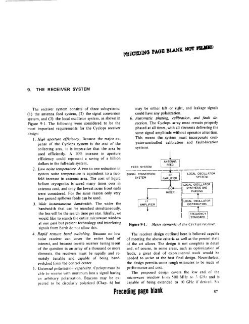
The receiver system consists <strong>of</strong> three subsystems:<br />
(1) the antenna feed system, (2) the signal conversion<br />
system, <strong>and</strong> (3) the local oscillator system, as shown in<br />
Figure 9-1. The following were considered to be the<br />
most important requirements for the <strong>Cyclops</strong> receiver<br />
design:<br />
1. High aperture efficiency. Because the major expense<br />
<strong>of</strong> the <strong>Cyclops</strong> system is the cost <strong>of</strong> the<br />
collecting area, it is imperative that the area be<br />
used efficiently. A 10% increase in aperture<br />
efficiency could represent a saving <strong>of</strong> a billion<br />
dollars in the full-scale system.<br />
2. Low noise temperature. A two to one reduction in<br />
system noise temperature is equivalent to a tw<strong>of</strong>old<br />
increase in antenna area. The cost <strong>of</strong> liquid<br />
helium cryogenics is saved many times over in<br />
antenna cost, <strong>and</strong> only the lowest noise front ends<br />
were considered. For the same reason only very<br />
low ground spillover feeds can be used.<br />
3. Wide instantaneous b<strong>and</strong>width. The wider the<br />
b<strong>and</strong>width that can be searched simultaneously,<br />
the less will be the search time per star. Ideally, we<br />
would like to search the entire microwave window<br />
at one pass but present technology <strong>and</strong> interfering<br />
signals from <strong>Earth</strong> do not allow this.<br />
4. RapM remote b<strong>and</strong> switching. Because no low<br />
noise receiver can cover the entire b<strong>and</strong> <strong>of</strong><br />
interest, <strong>and</strong> because on-site receiver tuning is out<br />
<strong>of</strong> the question in an array <strong>of</strong> a thous<strong>and</strong> or more<br />
elements, the receivers must be rapidly <strong>and</strong> remotely<br />
tunable <strong>and</strong> capable <strong>of</strong> being b<strong>and</strong>switched<br />
from the control center.<br />
5. Universal polarization capability. <strong>Cyclops</strong> must be<br />
able to receive with minimum loss a signal having<br />
an arbitrary polarization. Beacons may be expected<br />
to be circularly polarized (Chap. 6) but<br />
may be either left or right, <strong>and</strong> leakage signals<br />
could<br />
have any polarization.<br />
FEED<br />
SIGNAL<br />
6. Automatic phasing, calibration, <strong>and</strong> fault detection.<br />
The <strong>Cyclops</strong> array must remain properly<br />
phased at all times, with all elements delivering the<br />
same signal amplitude without operator attention.<br />
This means the system must incorporate computer-controlled<br />
calibration <strong>and</strong> fault-location<br />
systems.<br />
SYSTEM<br />
CONVERSION<br />
SYSTEM<br />
Figure 9-1.<br />
1<br />
ANTENNA<br />
FEED<br />
LRI_FF _R "_l LOCAL OSCILLATOR<br />
AMP I SYSTEM<br />
.._ !I LOCAL OSCILLATOR<br />
I LOCAL<br />
SYNTHESIS<br />
AND<br />
OSCILLATOR<br />
l AM#LFFIER DISTRIBUTION I<br />
IFREQUENCY<br />
I _ STANDARD ]<br />
Major elements <strong>of</strong> the <strong>Cyclops</strong> receiver.<br />
The receiver design outlined here is believed capable<br />
<strong>of</strong> meeting the above criteria as well as the present state<br />
<strong>of</strong> the art allows. The design is not complete in detail<br />
<strong>and</strong>, <strong>of</strong> course, in some areas, such as optimization <strong>of</strong><br />
feeds, a great deal <strong>of</strong> experimental work would be<br />
needed to arrive at the best final design. Nevertheless,<br />
the design permits some rough estimates to be made <strong>of</strong><br />
performance <strong>and</strong> cost.<br />
The proposed design covers the low end <strong>of</strong> the<br />
microwave window from 500 MItz to 3 Gttz <strong>and</strong> is<br />
capable <strong>of</strong> being extended to 10 GHz if desired. Six<br />
Preceding pageblank 87


