

Project Cyclops, A Design... - Department of Earth and Planetary ...
Project Cyclops, A Design... - Department of Earth and Planetary ...
Project Cyclops, A Design... - Department of Earth and Planetary ...

You also want an ePaper? Increase the reach of your titles
YUMPU automatically turns print PDFs into web optimized ePapers that Google loves.
ightness distributionoverthecommonfield<strong>of</strong>view<strong>of</strong><br />
theantennas. Finally,thetwo-dimensional Fouriertransform<strong>of</strong><br />
themeasured dataistakento getthedesired<br />
map.TheproposedVLAsystemwillusethistechnique,<br />
calledaperture synthesis. It is obvious that neither <strong>of</strong><br />
these methods produces a real-time image <strong>of</strong> the sky.<br />
<strong>and</strong> at an azimuth a will be received by an antenna at<br />
x,y with a delay.<br />
x sin a +y cos a<br />
rr(X,Y) = - sin 8 (36)<br />
The greater the resolution desired, the greater is the<br />
time required to map a given area <strong>of</strong> the sky. With the<br />
resolution available from the <strong>Cyclops</strong> array the times are<br />
very long indeed. Assume that we have 1000 dishes<br />
spread over an area 10 km in diameter, <strong>and</strong> operating at<br />
a wavelength <strong>of</strong> 10 cm, If we allow 3 dB gain fall<strong>of</strong>f at<br />
the edges <strong>of</strong> each elemental area scanned, the number <strong>of</strong><br />
resolvable directions is about 1.5 (Ird/X) 2 = 1.5×10 II<br />
(see Chap. 6). With an integration time <strong>of</strong> only 1 sec per<br />
elemental area scanned, it would take 1.5× 10¹¹ sec or<br />
about 5000 years to map the entire sky. Even to map an<br />
object such as M31 (the Andromeda galaxy)would take<br />
about 126 eight-hour observing days, or 4 months. But<br />
with 1000 elements in the array, we can form I000<br />
independent beams simultaneously, <strong>and</strong> thus map the<br />
whole sky in 5 years, or M31 in an hour.<br />
where c is the velocity <strong>of</strong> light. At the received<br />
frequency w r this delay causes a phase shift<br />
% = rrW r (37)<br />
The delay <strong>and</strong>, if the spectrum has not been inverted,<br />
the phase shift are preserved by all the heterodyning<br />
operations <strong>and</strong> thus are present at the IF outputs.<br />
Even with an imaging system, the field <strong>of</strong> view is<br />
limited by the beamwidth <strong>of</strong> the antenna elements.<br />
Moreover, in an array, there are additional grating lobes<br />
within this field that confuse the picture <strong>and</strong> reduce the<br />
usable field area by the filling factor. Thus, for the<br />
<strong>Cyclops</strong> array with a filling factor <strong>of</strong> 1/10, ten times as<br />
many fields <strong>of</strong> view would be needed to synthesize a<br />
picture <strong>of</strong> a given region as would be needed with a<br />
single 100-m dish. The advantage <strong>of</strong> the array is that the<br />
final picture contains 10,000 times the detail. Thus, the<br />
array with its 1000 dishes is 1000 times more powerful<br />
for map ing, as one should expect. In fact, if blurred<br />
areas in the map made with the single antenna are<br />
resolved into sharp points by the array, the integration<br />
time can be reduced, making the array even more<br />
powerful.<br />
General<br />
Principles<br />
To simplify our thinking let us initially assume that<br />
the <strong>Cyclops</strong> array is pointed at the zenith. A signal<br />
received from the zenith will then produce the same IF<br />
output signal at the central station from every antenna<br />
element.<br />
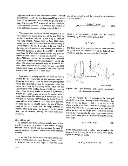
Let us take Y to be the north-south axis <strong>of</strong> the array<br />
<strong>and</strong> X to be the east-west axis as shown in Figure 11-I 6a.<br />
A signal received at a small angle _ from the zenith<br />
SIGNAL PLANE _ V _<br />
...."_ 0/<br />
IMAGE<br />
/<br />
PLANE<br />
Figure ll-16. (aj Antenna <strong>and</strong> source coordinate.<br />
[b ) Imaging coordinates.<br />
Let us imagine the IF outputs to be arranged<br />
physically in a plane, forming a small scale map <strong>of</strong> the<br />
array, so that in Figure ll-16b x' = ox <strong>and</strong>y' = oy<br />
where o is the scale factor. Now let us arrange a second<br />
lattice <strong>of</strong> points with coordinates u, v in a second plane,<br />
which we will call the image plane, <strong>and</strong> let us connect<br />
each <strong>of</strong> the IF outputs in the signal plane to every lattice<br />
point in the image plane via a transmission path having a<br />
phase shift<br />
_i = - k(ux + vy) (38)<br />
At the image plane point at radius r <strong>and</strong> at angle a, the<br />
phase will be _bi = -k r (u sin a + v cos a) while at the<br />
angle Ir + _ the phase will be<br />
¢i = kr (u sin a + v cos _) (39)<br />
142


