

Project Cyclops, A Design... - Department of Earth and Planetary ...
Project Cyclops, A Design... - Department of Earth and Planetary ...
Project Cyclops, A Design... - Department of Earth and Planetary ...

Create successful ePaper yourself
Turn your PDF publications into a flip-book with our unique Google optimized e-Paper software.
where 0 is the angle <strong>of</strong>f axis, <strong>and</strong> "Iv is the vth order<br />
Bessel function. Now f(O) = fUdA <strong>and</strong> is unity for all v.<br />
If v = 1, we have a constant illumination over the<br />
circular aperture. If v = 3/2 the amplitude has a<br />
hemispherical distribution, while the intensity 1/212 is a<br />
paraboloid. If v = 1 the amplitude has a paraboloidal<br />
distribution. Several distributions <strong>of</strong> this family are<br />
shown in Figure 9-3 <strong>and</strong> the corresponding radiation<br />
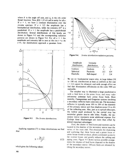
patterns are shown in Figure 9-4. For all v > 1 the<br />
amplitude <strong>and</strong> intensity fall to zero at the rim r = a. As<br />
u-+oo, the distributions approach a gaussian form.<br />
1.0 1_///7- -_-----7 _ T f 1 r !<br />
I kNNN_<br />
\\\\\\\. i<br />
41- \ \\\\x,_ .z<br />
4<br />
7to 2<br />
T 7 _ 7<br />
v=O<br />
-.4 ___ __ i<br />
0 2 4 6 8 I0<br />
2fro<br />
a =---g- 0<br />
Figure 9-4. Sonine distribution radiation patterns.<br />
3<br />
TrO 2<br />
Amplitude<br />
Intensity<br />
distribution distribution v r/<br />
5/2<br />
Uniform Uniform 1 1<br />
Spherical Parabolic 3/2 8/9<br />
Parabolic Bell-shaped 2 3/4<br />
2<br />
i7-0 2<br />
I<br />
-frO2<br />
2 4<br />
1/2 _ X_<br />
I I I l I<br />
.2 .4 ,6 .8 1.0 t.2 1.4<br />
Figure 9-3. The Sonine distributions.<br />
Applying equation (7) to these distributions we find<br />
that<br />
which gives the following values:<br />
mr<br />
0<br />
2v- 1<br />
= _ (12)<br />
1/2<br />
We see no fundamental reason why, in large dishes (50<br />
to 100 m), distributions at least as uniform as the case<br />
v = 3/2 cannot be obtained, <strong>and</strong> with enough effort we<br />
feel that illumination efficiencies on the order 90% are<br />
realizable.<br />
The simplest way to illuminate a large paraboloid is<br />
with a feed horn at the prime focus, <strong>and</strong> many radio<br />
astronomy antennas have prime focus feeds. More<br />
recently, Cassegrainian <strong>and</strong> Gregorian systems involving<br />
a secondary reflector have come into use. The secondary<br />
reflector is typically some 10% to 20% <strong>of</strong> the diameter<br />
<strong>of</strong> the primary mirror <strong>and</strong> thus shadows some 1% to 4%<br />
<strong>of</strong> the collecting area. Also, just as in optical telescopes,<br />
the hollow pupil produced by the central stop has<br />
somewhat greater near-in side lobes. Finally, the secondary<br />
mirror represents some additional expense. For<br />
<strong>Cyclops</strong> these disadvantages are more than <strong>of</strong>fset by<br />
several important advantages.<br />
First, the cluster <strong>of</strong> feed horns <strong>and</strong> receivers can be<br />
located in the shadow <strong>of</strong> the secondary mirror near the<br />
vertex <strong>of</strong> the main dish. This eliminates the shadowing<br />
<strong>and</strong> scattering that these horns <strong>and</strong> a prime focus receiver<br />
house would produce, allows convenient access to<br />
the receiver house, <strong>and</strong> greatly reduces the cabling <strong>and</strong><br />
piping costs. Figure 9-5 shows various possible arrangements<br />
for clusters <strong>of</strong> feed horns disposed in the shadow<br />
<strong>of</strong> the secondary mirror. Off-axis feeds are obtained by<br />
tilting the _condary mirror.<br />
90


