

Project Cyclops, A Design... - Department of Earth and Planetary ...
Project Cyclops, A Design... - Department of Earth and Planetary ...
Project Cyclops, A Design... - Department of Earth and Planetary ...

You also want an ePaper? Increase the reach of your titles
YUMPU automatically turns print PDFs into web optimized ePapers that Google loves.
There are 24 members in the base structure (not<br />
including the piston).<br />
For the geometry chosen, the lengths <strong>of</strong> the members<br />
are as follows:<br />
No. <strong>of</strong> Members Length (ft)<br />
3 61.5<br />
3 52.0<br />
3 42.0<br />
3 45.0<br />
6 54.5<br />
6 58.7<br />
The structure configuration is well suited for mass<br />
production. The basic element consists <strong>of</strong> three identical<br />
truss elements, which can be factory assembled <strong>and</strong><br />
erected with a minimum <strong>of</strong> field welding.<br />
Weight <strong>and</strong> Cost<br />
A preliminary weight estimate <strong>of</strong> the structure may<br />
be obtained without a detailed structural design effort<br />
by requiring that all members have L/r ratio less than<br />
200 (r = radius <strong>of</strong> gyration <strong>of</strong> the member). Rough<br />
calculations indicate that 8 in SC 40 pipe will meet this<br />
requirement <strong>and</strong> should be strong enough. Based on the<br />
use <strong>of</strong> this pipe (28.56 lb/ft), a total weight <strong>of</strong> base<br />
structure W is easily found. We obtain I¢ = 36,600 lb.<br />
Allowing an additional 10% for fittings we obtain a base<br />
weight on the order <strong>of</strong> 41,000 lb. Note that this weight<br />
does not include bearings, wheel <strong>and</strong> track, or pistons.<br />
At a material cost <strong>of</strong> $0.20/lb, we find that the basic<br />
steelwork will cost $8,200 per base structure. It seems<br />
likely (although no figures can be provided at this time)<br />
that the assembled structure (again excluding piston,<br />
bearing, <strong>and</strong> wheel <strong>and</strong> track) would cost $16,000 to<br />
$24,000 if mass produced. No calculations were made<br />
for a 100 meter dish. If the design is practical for this<br />
larger size the material cost alone would be on the order<br />
<strong>of</strong> $300,000.<br />
<strong>Design</strong><br />
Considerations<br />
If we require that the center <strong>of</strong> the dish at zenith be<br />
located directly over the central bearing <strong>of</strong> the base<br />
structure, we find that the maximum dish radius that<br />
can be accommodated is Rma x --- 68 ft. The limiting<br />
factor is backup structure interference with ground at<br />
maximum angle from zenith.<br />
The structure is statically determinate, carries its<br />
loading by tension or compression in all members, <strong>and</strong> is<br />
completely triangularized; no stability problems should<br />
occur. Horizontal loads are carried by the central<br />
bearing, while vertical loading is carried by the three<br />
wheel supports. Drive for the azimuth positioning is<br />
provided by powering the wheels. Became side loads are<br />
carried by the central bearing, the wheel <strong>and</strong> track<br />
tolerances in the horizontal plane are not critical. In<br />
fact, it may not be necessary to provide more than a<br />
reasonably level roadway since final pointing adjustments<br />
in elevation can be made by the elevation piston if<br />
compensating feedback is provided.<br />
A better estimate <strong>of</strong> the cost cannot be obtained until<br />
strength calculations are complete for the design Ioadings.<br />
Such strength calculations will yield requirements<br />
on piston, bearing, <strong>and</strong> wheel <strong>and</strong> track assemblies; only<br />
after this is completed can a cost estimate <strong>of</strong> these<br />
members be obtained.<br />
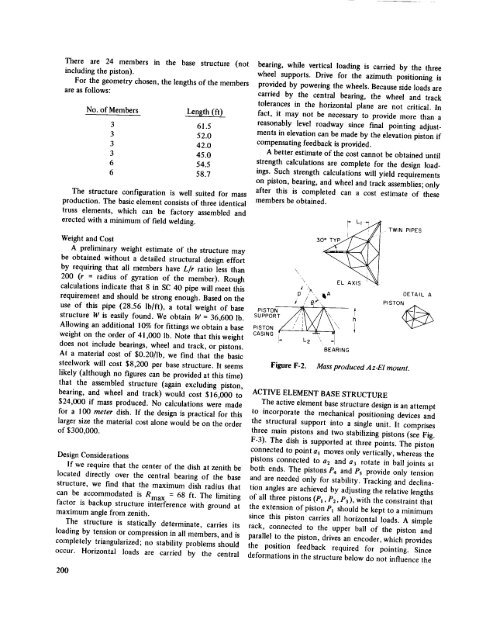
PI TO<br />
\\<br />
\<br />
30* TYP I -'<br />
TWIN<br />
PIPES<br />
p_/i'_', IIA DETAIL A<br />
SUPPORT //' '\\// _, h<br />
PISTON / /' I W _\\<br />
CASING ? -'_ ,, 1<br />
BEARING<br />
Figure F-2. Mass produced Az-El mount.<br />
ACTIVE ELEMENT BASE STRUCTURE<br />
The active element base structure design is an attempt<br />
to incorporate the mechanical positioning devices <strong>and</strong><br />
the structural support into a single unit. It comprises<br />
three main pistons <strong>and</strong> two stabilizing pistons (see Fig.<br />
F-3). The dish is supported at three points. The piston<br />
connected to point a_ moves only vertically, whereas the<br />
pistons connected to a2 <strong>and</strong> a3 rotate in ball joints at<br />
both ends. The pistons P4 <strong>and</strong> Ps provide only tension<br />
<strong>and</strong> are needed only for stability. Tracking <strong>and</strong> declination<br />
angles are achieved by adjusting the relative lengths<br />
<strong>of</strong> all three pistons (P_, P2, P3), with the constraint that<br />
the extension <strong>of</strong> piston P1 should be kept to a minimum<br />
since this piston carries all horizontal loads. A simple<br />
rack, connected to the upper ball <strong>of</strong> the piston <strong>and</strong><br />
parallel to the piston, drives an encoder, which provides<br />
the position feedback required for pointing. Since<br />
deformations in the structure below do not influence the<br />
I<br />
200


