

Project Cyclops, A Design... - Department of Earth and Planetary ...
Project Cyclops, A Design... - Department of Earth and Planetary ...
Project Cyclops, A Design... - Department of Earth and Planetary ...

Create successful ePaper yourself
Turn your PDF publications into a flip-book with our unique Google optimized e-Paper software.
only±0.07;_ up to p[a = 1.77. Beyond this the error<br />
increases to about X/4 at p[2 = 2, but there is very little<br />
signal plane area at this value <strong>of</strong> the abscissa. Thus, the<br />
image quality should be quite good. The situation<br />
rapidly improves as we go to higher frequencies.<br />
• _ I I I T I' I I I I<br />
(o)<br />
pyramid at the highest frequency used. Alternatively,<br />
the radiative imager could use short helical antennas.<br />
These also permit broadb<strong>and</strong> operation <strong>and</strong> the two<br />
polarizations used could then be left <strong>and</strong> right h<strong>and</strong>ed<br />
circular. An advantage <strong>of</strong> helical antennas is that the<br />
phase <strong>of</strong> the radiation can be changed simply by rotating<br />
the helix about its axis. This phase changing capability<br />
could well simplify the construction <strong>of</strong> the imager <strong>and</strong><br />
reduce the phase tolerances needed since it would be<br />
easy to trim each element.<br />
f.,c,_ \ \ \ \<br />
-_ I _ I I I I I I I<br />
(b)<br />
.I<br />
O. IOta<br />
-.I 1. 57m<br />
f • 1.42CHZ<br />
-.2 i i i i t<br />
.I I( ' _ ' ' ' ' _ ' '<br />
--. I I I I I I I I _ I _I<br />
(d)a IOta, /.120m<br />
f-" 3GHZ<br />
--.I I I I I I I I I I I_"I<br />
o I 2<br />
Figure 11-20. Spherical aberrations with parabolic<br />
p/o<br />
delay.<br />
Further studies might reveal that some other system,<br />
such as using a fixed<br />
curved signal array plus variable RF<br />
delay, would give improved results, but the system<br />
described seems entirely adequate. We are, after all, not<br />
attempting high-resolution imaging by optical st<strong>and</strong>ards;<br />
there are only 32 independent picture elements per line.<br />
Another advantage <strong>of</strong> microwave imaging is that both<br />
polarizations can be imaged simultaneously. It is a<br />
simple matter to mix the IF signals (if necessary) to<br />
obtain signals representing vertical <strong>and</strong> horizontal polarization.<br />
They can then (after heterodyning to the imaging<br />
frequency) be radiated as such by crossed dipoles or<br />
loops. Good broadb<strong>and</strong> performances can be realized<br />
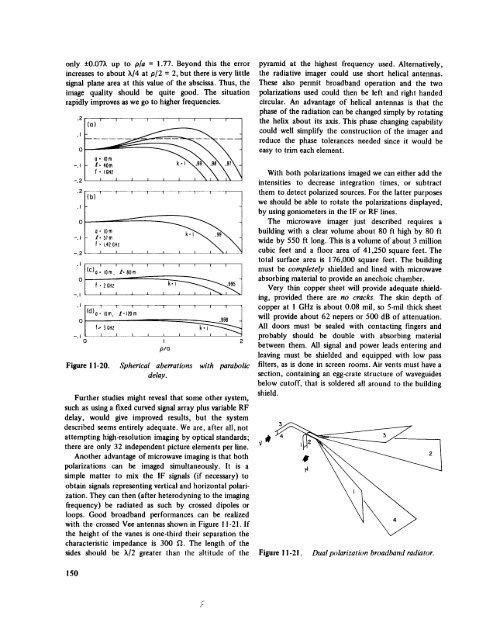
with the crossed Vee antennas shown in Figure 11-21. If<br />
the height <strong>of</strong> the vanes is one-third their separation the<br />
characteristic impedance is 300 _. The length <strong>of</strong> the<br />
sides should be _/2 greater than the altitude <strong>of</strong> the<br />
With both polarizations imaged we can either add the<br />
intensities to decrease integration times, or subtract<br />
them to detect polarized sources. For the latter purposes<br />
we should be able to rotate the polarizations displayed,<br />
by using goniometers in the IF or RF lines.<br />
The microwave imager just described requires a<br />
building with a clear volume about 80 ft high by 80 ft<br />
wide by 550 ft long. This is a volume <strong>of</strong> about 3 million<br />
cubic feet <strong>and</strong> a floor area <strong>of</strong> 41,250 square feet. The<br />
total surface area is 176,000 square feet. The building<br />
must be completely shielded <strong>and</strong> lined with microwave<br />
absorbing material to provide an anechoic chamber.<br />
Very thin copper sheet will provide adequate shielding,<br />
provided there are no cracks. The skin depth <strong>of</strong><br />
copper at l GHz is about 0.08 mil, so 5-mil thick sheet<br />
will provide about 62 nepers or 500 dB <strong>of</strong> attenuation.<br />
All doors must be sealed with contacting fingers <strong>and</strong><br />
probably should be double with absorbing material<br />
between them. All signal <strong>and</strong> power leads entering <strong>and</strong><br />
leaving must be shielded <strong>and</strong> equipped with low pass<br />
filters, as is done in screen rooms. Air vents must have a<br />
section, containing an egg-crate structure <strong>of</strong> waveguides<br />
below cut<strong>of</strong>f, that is soldered all around to the building<br />
shield.<br />
3<br />
Figure I 1-21. Dual polarization broadb<strong>and</strong> radiator.<br />
150


