

Project Cyclops, A Design... - Department of Earth and Planetary ...
Project Cyclops, A Design... - Department of Earth and Planetary ...
Project Cyclops, A Design... - Department of Earth and Planetary ...

Create successful ePaper yourself
Turn your PDF publications into a flip-book with our unique Google optimized e-Paper software.
arenowsentoutover the cable. At the antenna station<br />
the incoming frequency <strong>and</strong> the two outgoing frequencies<br />
are added to obtain col. In principle, the order<br />
<strong>of</strong> addition is immaterial, but greater freedom from<br />
spurious products will obtain if the two inputs to<br />
any mixer differ considerably in frequency. Thus we<br />
can add col to (coo/2) + 5 <strong>and</strong> then add the sum to<br />
(coo 2) - 5 - col as shown, but we should not add<br />
col to (coo/E) - 5 - col <strong>and</strong> then add the sum,<br />
(OOo/2) - 5 to (oo0/2) + 5, since 5 will be small, or zero.<br />
However, we can subtract these two inputs in a mixer<br />
as shown at the right <strong>of</strong> Figure 9-14 to obtain the<br />
frequency 26. If the remote oscillator is made voltage<br />
controllable, we can now apply the output <strong>of</strong> the<br />
rightmost mixer, after appropriate low-pass filtering, as<br />
the control signal to this oscillator <strong>and</strong> thus phase lock<br />
the entire system, which sets 5 = 0. In the absence <strong>of</strong><br />
cable dispersion <strong>and</strong> reflections, there will be zero phase<br />
error.<br />
If, for example,<br />
(,Oo/2 = 500 GHz <strong>and</strong> cot = 200 GHz,<br />
then (coo/2) - cot = 300 GHz <strong>and</strong> the three frequencies<br />
on the cable are widely separated; no narrow filters are<br />
needed to isolate them. The problem is that they are too<br />
widely separated. The directional couplers must cover a<br />
wide b<strong>and</strong> <strong>and</strong> dispersion in the cable produces a<br />
significant error.<br />
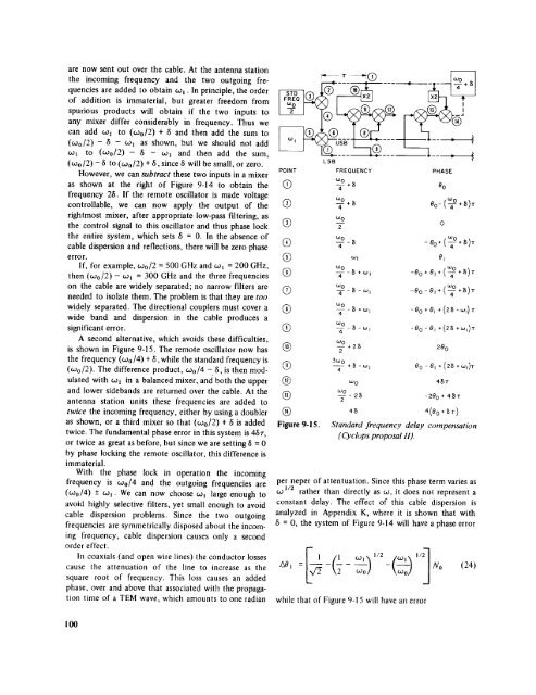
A second alternative, which avoids these difficulties,<br />
is shown in Figure 9-15. The remote oscillator now has<br />
the frequency (COo/4) + 5, while the st<strong>and</strong>ard frequency is<br />
(600/2). The difference product, coo/4 - 5, is then modulated<br />
with co, in a balanced mixer, <strong>and</strong>' both the upper<br />
<strong>and</strong> lower sideb<strong>and</strong>s are returned over the cable. At the<br />
antenna station units these frequencies are added to<br />
twice the incoming frequency, either by using a doubler<br />
as shown, or a third mixer so that (ooo/2) + 5 is added<br />
twice. The fundamental phase error in this system is 45r,<br />
or twice as great as before, but since we are setting/5 = 0<br />
by phase locking the remote oscillator, this difference is<br />
immaterial.<br />
With the phase lock in operation the incoming<br />
frequency is coo/4 <strong>and</strong> the outgoing frequencies are<br />
(coo/4) -+ co,- We can now choose col large enough to<br />
avoid highly selective filters, yet small enough to avoid<br />
cable dispersion problems. Since the two outgoing<br />
frequencies are symmetrically disposed about the incoming<br />
frequency, cable dispersion causes only a second<br />
order effect.<br />
In coaxials (<strong>and</strong> open wire lines) the conductor losses<br />
cause the attenuation <strong>of</strong> the line to increase as the<br />
square root <strong>of</strong> frequency. This loss causes an added<br />
phase, over <strong>and</strong> above that associated with the propagation<br />
time <strong>of</strong> a TEM wave, which amounts to one radian<br />
POINT<br />
(i)<br />
LSB<br />
FREQUENCY<br />
toO<br />
-¥*_<br />
w 0<br />
toO<br />
® T<br />
@<br />
@<br />
too<br />
-a--8<br />
too<br />
to,<br />
_--_+_,<br />
coo<br />
k23 -T -8 -to I<br />
too<br />
(Z) q- - _ - ",<br />
®<br />
@<br />
Figure 9-15.<br />
_0<br />
to O<br />
+8 -co I<br />
too<br />
PHASE<br />
Oo<br />
0<br />
-Oo+(T+<br />
81<br />
tOO<br />
-Oo+O,+(_+8)z<br />
-Oo- O, + (-_<br />
g)T<br />
+_)r<br />
-Oo +e, + (28-to,)<br />
-80 -8 I + (2_ +(.Oi)<br />
280<br />
80-81 +(28+to I<br />
48"r<br />
--280 + 48"r<br />
4(80+_T )<br />
St<strong>and</strong>ard frequency delay compensation<br />
(<strong>Cyclops</strong> proposal II).<br />
per neper <strong>of</strong> attentuation. Since this phase term varies as<br />
co 1/2 rather than directly as co, it does not represent a<br />
constant delay. The effect <strong>of</strong> this cable dispersion is<br />
analyzed in Appendix K, where it is shown that with<br />
6 = 0, the system <strong>of</strong> Figure 9-14 will have a phase error<br />
A01 = -<br />
while that <strong>of</strong> Figure 9-1 5 will have an error<br />
No (24)<br />
T<br />
100


