Project Cyclops, A Design... - Department of Earth and Planetary ...
Project Cyclops, A Design... - Department of Earth and Planetary ...
Project Cyclops, A Design... - Department of Earth and Planetary ...
You also want an ePaper? Increase the reach of your titles
YUMPU automatically turns print PDFs into web optimized ePapers that Google loves.
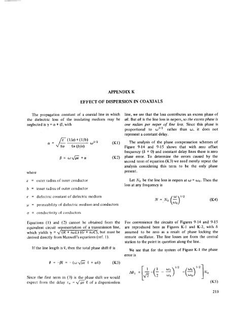
APPENDIXK<br />
EFFECTOF DISPERSION IN COAXIALS<br />
The propagation constant <strong>of</strong> a coaxial line in which<br />
the dielectric loss <strong>of</strong> the insulating medium may be<br />
neglected<br />
is 7 = a + ifl, with<br />
line, we see that the loss contributes an excess phase <strong>of</strong><br />
t_. But t_ is the line loss in nepers, so the excess phase is<br />
one radian per neper <strong>of</strong> line loss. Since this phase is<br />
proportional to wl/2 rather than co, it does not<br />
represent a constant delay.<br />
v/_o_o( i/a) + ( l/b)<br />
a = £n (b/a)<br />
(DI/2<br />
(KI)<br />
(K2)<br />
The analysis <strong>of</strong> the phase compensation schemes <strong>of</strong><br />
Figure 9-14 <strong>and</strong> 9-15 shows that with zero <strong>of</strong>fset<br />
frequency (6 = 0) <strong>and</strong> constant delay lines there is zero<br />
phase error. To determine the errors caused by the<br />
second term <strong>of</strong> equation (K3) we need merely repeat the<br />
analysis considering this term to be the only phase<br />
where<br />
present.<br />
a = outer radius <strong>of</strong> inner conductor<br />
b = inner radius <strong>of</strong> outer conductor<br />
e = dielectric constant <strong>of</strong> dielectric medium<br />
/a = permeability <strong>of</strong> dielectric medium <strong>and</strong> conductors<br />
Let No be the line loss in nepers at co = Wo. Then the<br />
loss at any frequency<br />
is<br />
N = No -- O.2 _1/2<br />
(K4)<br />
, \_o!<br />
o = conductivity <strong>of</strong> conductors<br />
Equations (1) <strong>and</strong> (2) cannot be obtained from the<br />
equivalent circuit representation <strong>of</strong> a transmission line,<br />
which yields "y = x/ (R + iwL ) (G + i_oC), but must be<br />
derived directly from Maxwell's equations (ref. 1).<br />
If the line length is £, then the total phase shift 0 is<br />
For convenience the circuits <strong>of</strong> Figures 9-14 <strong>and</strong> 9-15<br />
are reproduced here as Figures K-1 <strong>and</strong> K-2, with /5<br />
assumed to be zero as a result <strong>of</strong> phase locking the<br />
remote oscillator. The line losses are from the central<br />
station to the point in question along the line.<br />
error<br />
We see that for the system <strong>of</strong> Figure K-I the phase<br />
is<br />
0 = -/3£ = -(co V_ £ + c_Q) (K3)<br />
Since the first term in (3) is tile phase shift we would<br />
expect from the delay % = _ £ <strong>of</strong> a dispersionless<br />
A01<br />
¢.0i._1 _ 1/2 .I/2-IIN0<br />
_o/ x,6°<strong>of</strong> J<br />
(K5)<br />
213


