

Project Cyclops, A Design... - Department of Earth and Planetary ...
Project Cyclops, A Design... - Department of Earth and Planetary ...
Project Cyclops, A Design... - Department of Earth and Planetary ...

Create successful ePaper yourself
Turn your PDF publications into a flip-book with our unique Google optimized e-Paper software.
COAXIAL<br />
LINE<br />
DIRECTIONALCOUPLER<br />
FREQUENCIES<br />
MHZ<br />
INCOMING OUTGOING RECOVERY<br />
I 250<br />
I<br />
I 6.25<br />
275<br />
225<br />
6.875<br />
5.625<br />
kO00<br />
25<br />
__<br />
_-_iI BRANCH LINES _<br />
I<br />
I<br />
REPEATER<br />
:__<br />
MAIN<br />
TRUNK<br />
LINES<br />
M = MODULATOR<br />
UNIT<br />
\<br />
ISTA_<br />
A = ANTENNA STATION UNIT<br />
T : TERMINATOR UNIT<br />
OUT<br />
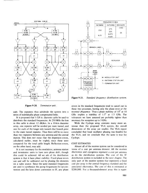
Figure 9-21. St<strong>and</strong>ard frequency distribution system.<br />
Figure 9-20. Terminator unit.<br />
unit. The repeaters thus subdivide the system into a<br />
series <strong>of</strong> individually phase compensated links.<br />
It is proposed that I-5/8 in. diameter cable be used to<br />
distribute the st<strong>and</strong>ard frequencies. At 250 MHz the loss<br />
in this cable is about 12 dB/km. In a l O-km diameter<br />
array, one repeater will be needed per main tunnel, <strong>and</strong><br />
one for each <strong>of</strong> the longer side tunnels that branch prior<br />
to the main tunnel repeater. Thus there will be no more<br />
than two repeaters between any antenna <strong>and</strong> the central<br />
station. This does not mean that the dispersion errors,<br />
calculated earlier, must be tripled, since these were<br />
computed for the total cable length. Reflection errors,<br />
on the other h<strong>and</strong>, may add.<br />
It is not necessary for the modulator, antenna station<br />
<strong>and</strong> terminator units to have zero phase shift, though<br />
this could be achieved. All we ask <strong>of</strong> the distribution<br />
system is that it have phase stability. Fixed phase errors<br />
can <strong>and</strong> will be calibrated out by phasing the elements<br />
on a radio source. Since the same st<strong>and</strong>ard frequencies<br />
are used to synthesize the pump frequencies for up-conversion<br />
<strong>and</strong> the later down conversion to IF, any phase<br />
errors in the st<strong>and</strong>ard frequencies tend to cancel out in<br />
these two processes, leaving only the phase error at the<br />
received frequency. Thus a phase stability <strong>of</strong> 10° at !0<br />
GHz implies a stability <strong>of</strong> i.5 ° at 1.5 GHz. The<br />
tolerances we have assumed are probably tighter than<br />
necessary for reception up to 3 GHz.<br />
While the <strong>Cyclops</strong> array contains many more antennas<br />
than the proposed VLA system, the overall<br />
dimensions <strong>of</strong> the array are smaller. The VLA report<br />
concluded that local oscillator phasing was feasible for<br />
the VLA, <strong>and</strong> we conclude that the same is true for<br />
<strong>Cyclops</strong>.<br />
COST<br />
ESTIMATES<br />
Almost all <strong>of</strong> the receiver system can be considered in<br />
terms <strong>of</strong> a cost per antenna element. All the receiver<br />
electronics <strong>and</strong> cryogenics represent a cost per antenna<br />
as do the distribution systems. The cost <strong>of</strong> the IF<br />
distribution system is included in the next chapler. The<br />
only part <strong>of</strong> the receiver system tha! represents a Fixed<br />
cost per array is the central frequency st<strong>and</strong>ard <strong>and</strong> lhe<br />
associated electronics. The cost <strong>of</strong> this is estimated al<br />
$200,000. For a thous<strong>and</strong>-element array this is equiv-<br />
103


