

Project Cyclops, A Design... - Department of Earth and Planetary ...
Project Cyclops, A Design... - Department of Earth and Planetary ...
Project Cyclops, A Design... - Department of Earth and Planetary ...

Create successful ePaper yourself
Turn your PDF publications into a flip-book with our unique Google optimized e-Paper software.
A02 .... + No (25)<br />
(i C 1<br />
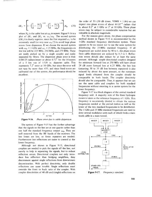
where No is the cable loss at Wo in nepers. Figure 9-16 is a<br />
plot <strong>of</strong> A0t <strong>and</strong> A02 vs. w_/co0. The second system<br />
(A0z) is clearly superior, since the first required wl tobe<br />
extremely small (or very near coo/2) to avoid large phase<br />
errors from dispersion. If we choose the second system<br />
with co0 = 1 GHz <strong>and</strong> cJt = 25 MHz, the frequencies on<br />
the line will be 225 MHz, 250 MHz, <strong>and</strong> 275 MHz. These<br />
are easily picked up by a single coupler <strong>and</strong> easily<br />
separated by filters. The dispersion phase error is then<br />
0.00125 radians/neper or about 0.72 ° for the 14 nepers<br />
<strong>of</strong> a 5 km run <strong>of</strong> 1-5/8 in. diameter cable. This<br />
represents 7.2 ° error at l0 GHz, but since the error will<br />
not vary by more than -+5%, <strong>and</strong> since fixed errors are<br />
calibrated out <strong>of</strong> the system, the performance should be<br />
excellent.<br />
_.3<br />
o<br />
_.2<br />
O<br />
treybJ<br />
.I<br />
32<br />
Figure 9-16.<br />
.I .2 .3 .4 .5<br />
co<br />
I/oJO<br />
Phase error due<br />
to cable dispersion.<br />
the order <strong>of</strong> 3% (30 dB down, VSWR = 1.06) we can<br />
expect rms phase errors <strong>of</strong> about 4XlO -2 radian-that<br />
is, about 0.2 ° at 1 GHz or 2° at 10 GHz. These phase<br />
errors may be subject to considerable variation but are<br />
tolerable in absolute magnitude.<br />
For the reasons given above, the phase compensation<br />
method shown in Figure 9-15 is recommended for the<br />
I-GHz st<strong>and</strong>ard frequency distribution system. There<br />
appears to be no reason not to use the same system for<br />
distributing the 25-MHz st<strong>and</strong>ard frequency. If all<br />
frequencies are scaled down by 40 to 1, the phase errors<br />
from cable dispersion are reduced by 6.3 to 1. Reflection<br />
errors should also reduce by at least the same<br />
amount. Although simple directional couplers designed<br />
for minimum forward loss at 250 MHz will have about<br />
28 dB more forward loss at 6.25 MHz, the line loss<br />
(assuming 30 to 35 dB loss between repeaters) is also<br />
reduced by about the same amount, so the minimum<br />
signal levels obtained from the coupler should be<br />
comparable in both b<strong>and</strong>s. The coupler directivity<br />
should also be comparable. Thus, it appears that we can<br />
use the same cable <strong>and</strong> couplers for both st<strong>and</strong>ard<br />
frequencies without resorting to a carrier system for the<br />
lower frequency.<br />
Figure 9-17 is a block diagram <strong>of</strong> the central st<strong>and</strong>ard<br />
frequency unit. A majority vote <strong>of</strong> the three hydrogen<br />
masers is taken as tire reference frequency <strong>of</strong> 1 GHz. This<br />
frequency is successively divided to obtain tire various<br />
frequencies needed at the central station as well as the<br />
lower <strong>of</strong> the two st<strong>and</strong>ard frequencies to be distributed.<br />
The 1 GHz <strong>and</strong> 25 MHz st<strong>and</strong>ard frequencies are used to<br />
drive several modulator units each <strong>of</strong> which feeds a main<br />
trunk cable in a main tunnel.<br />
The system <strong>of</strong> Figure 9-15 has the further advantage<br />
that the signals on the line are at one quarter rather than<br />
one half the st<strong>and</strong>ard frequency output w0. They are<br />
well removed from the RF b<strong>and</strong>s <strong>of</strong> the receivers. The<br />
line losses are less, so fewer repeaters are needed.<br />
Furthermore line reflections are easier to control at the<br />
lower<br />
frequency.<br />
Although not shown in Figure 9-15, directional<br />
couplers are needed to pick the signals <strong>of</strong>f the line, not<br />
merely to help in separating the signals, but to reduce<br />
reflection errors. Directional couplers not only introduce<br />
less reflection than bridging amplifiers, they<br />
discriminate against single reflections from downstream<br />
discontinuities. With perfect directivity, only double<br />
reflections can cause trouble. Single reflections must<br />
override the front to back ratio <strong>of</strong> the coupler. With<br />
coupler direclivities <strong>of</strong> 40 dB <strong>and</strong> (single) reflections on<br />
LOCAL<br />
DISTRIBUTION<br />
'<br />
4<br />
ii<br />
250MHz<br />
IGHZ<br />
_-_-7<br />
OTHER STD L _r_J<br />
FREQS.<br />
........ J<br />
Figure 9-17.<br />
;IC ]<br />
Frequency<br />
I GHZ<br />
25 MHz<br />
IP<br />
P<br />
st<strong>and</strong>ard.<br />
TO<br />
MODULATOR<br />
UNITS<br />
101


