

Project Cyclops, A Design... - Department of Earth and Planetary ...
Project Cyclops, A Design... - Department of Earth and Planetary ...
Project Cyclops, A Design... - Department of Earth and Planetary ...

Create successful ePaper yourself
Turn your PDF publications into a flip-book with our unique Google optimized e-Paper software.
addedto theother IF channel. The two IF b<strong>and</strong>s, one<br />
extending from 75 to 175 MHz <strong>and</strong> the other from 325<br />
to 425 MHz, are then combined with the 250-MHz pilot<br />
frequency for transmission over the coaxial cable.<br />
arrange to have each IF b<strong>and</strong> experience the same cable<br />
loss <strong>and</strong> dispersion. In fact, we would like this to be true<br />
for each frequency within each IF b<strong>and</strong>.<br />
With straight through transmission the loss experienced<br />
by any frequency is<br />
E fO<br />
S = SO = SOVq-z-& (5)<br />
f) 1/2<br />
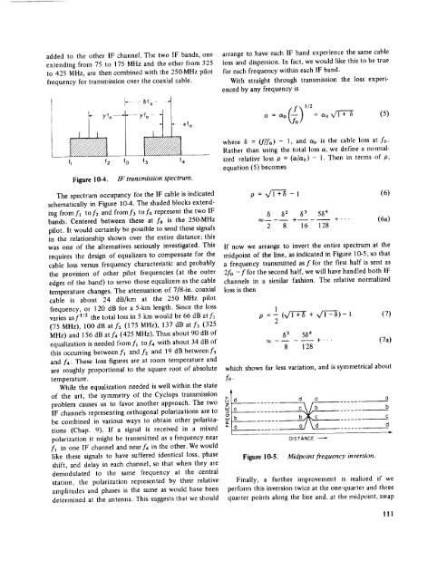
Figure 10-4. IF transmission spectrum.<br />
The spectrum occupancy for the IF cable is indicated<br />
schematically in Figure 10-4. The shaded blocks extending<br />
from fl to f2 <strong>and</strong> from f3 to f4 represent the two IF<br />
b<strong>and</strong>s. Centered between these at fo is the 250-MHz<br />
pilot. It would certainly be possible to send these signals<br />
in the relationship shown over the entire distance; this<br />
was one <strong>of</strong> the alternatives seriously investigated. This<br />
requires the design <strong>of</strong> equalizers to compensate for the<br />
cable loss versus frequency characteristic <strong>and</strong> probably<br />
the provision <strong>of</strong> other pilot frequencies (at the outer<br />
edges <strong>of</strong> the b<strong>and</strong>) to servo those equalizers as the cable<br />
temperature changes. The attenuation <strong>of</strong> 7/8-in. coaxial<br />
cable is about 24 dB/km at the 250 MHz pilot<br />
frequency, or 120 dB for a 5-km length. Since the loss<br />
varies as/1/2 the total loss in 5 km would be 66 dB at fl<br />
(75 MHz), 100 dB at f2 (175 MHz), 137 dB at f3 (325<br />
MHz) <strong>and</strong> 156 dB at f4 (425 MHz). Thus about 90 dB <strong>of</strong><br />
equalization is needed from f_ to f4 with about 34 dB <strong>of</strong><br />
this occurring between fl <strong>and</strong> f2 <strong>and</strong> 19 dB betweenf3<br />
<strong>and</strong>/"4. These loss figures are at room temperature <strong>and</strong><br />
are roughly proportional to the square root <strong>of</strong> absolute<br />
temperature.<br />
While the equalization needed is well within the state<br />
<strong>of</strong> the art, the symmetry <strong>of</strong> the <strong>Cyclops</strong> transmission<br />
problem causes us to favor another approach. The two<br />
IF channels representing orthogonal polarizations are to<br />
be combined in various ways to obtain other polarizations<br />
(Chap. 9). If a signal is received in a mixed<br />
polarization it might be transmitted as a frequency near<br />
f_ in one IF channel <strong>and</strong> near f4 in the other. We would<br />
like these signals to have suffered identical loss, phase<br />
shift, <strong>and</strong> delay in each channel, so that when they are<br />
demodulated to the same frequency at the central<br />
station, the polarization represented by their relative<br />
amplitudes <strong>and</strong> phases is the same as would have been<br />
determined at the antenna. This suggests that we should<br />
f4<br />
where 8 = (fifo) - 1, <strong>and</strong> So is the cable loss at fo-<br />
Rather than using the total loss s, we define a normalized<br />
relative loss P = (a/s0) - 1. Then in terms <strong>of</strong> p,<br />
equation<br />
(5) becomes<br />
p = X/1+5 -1 (6)<br />
8 82 53 564<br />
_---<br />
2 8<br />
+<br />
16 128<br />
+"" (6a)<br />
If now we arrange to invert the entire spectrum at the<br />
midpoint <strong>of</strong> the line, as indicated in Figure 10-5, so that<br />
a frequency transmitted as [ for the first half is sent as<br />
2fo -]'for the second half, we will have h<strong>and</strong>led both 1F<br />
channels in a similar fashion. The relative normalized<br />
loss is then<br />
1<br />
P =2 (_/1+5 + 41-5)-I (7)<br />
52 554<br />
....<br />
8 128<br />
+"" (7a)<br />
which shows far less variation, <strong>and</strong> is symmetrical about<br />
fo.<br />
_<br />
c_c_d<br />
"-to o<br />
...... 21<br />
DISTANCE<br />
Figure 10-5. Midpoint frequency inversion.<br />
Finally, a further improvement is realized if we<br />
perform this inversion twice at the one-quarter <strong>and</strong> three<br />
quarter points along the line <strong>and</strong>, at the midpoint, swap<br />
o<br />
!!1


