Project Cyclops, A Design... - Department of Earth and Planetary ...
Project Cyclops, A Design... - Department of Earth and Planetary ...
Project Cyclops, A Design... - Department of Earth and Planetary ...
You also want an ePaper? Increase the reach of your titles
YUMPU automatically turns print PDFs into web optimized ePapers that Google loves.
3's = unitcost<strong>of</strong> signal planelectronics<br />
3'j = unitcost<strong>of</strong> junction<br />
plane electronics<br />
3'i = unit cost <strong>of</strong> image plane electronics<br />
3"c = unit cost per cable<br />
nj = number <strong>of</strong> junctions<br />
N = number <strong>of</strong> cables<br />
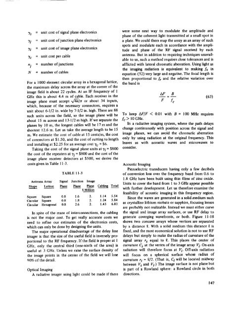
For a 1000 element circular array in a hexagonal lattice,<br />
the maximum delay across the array at the corner <strong>of</strong> the<br />
image field is about 22 cycles. At an IF frequency <strong>of</strong> 1<br />
GHz this is about 4.4 m <strong>of</strong> cable. Each receiver in the<br />
image plane must accept x/4-ff[rr or about 34 inputs,<br />
which, because <strong>of</strong> the necessary connectors, requires a<br />
unit about 6-1/2 in. wide by 7-1/2 in. high. There are 88<br />
such units across the field, so the image plane will be<br />
about 15 m across <strong>and</strong> 13-1/2 m high. lfwe separate the<br />
planes by 10 m, the longest cables will be 17 m <strong>and</strong> the<br />
shortest 12.6 m. Let us take the average length to be 15<br />
m. We estimate the cost <strong>of</strong> cable at 15 cents/m, the cost<br />
<strong>of</strong> connectors at $1.50, <strong>and</strong> the cost <strong>of</strong> cutting to length<br />
<strong>and</strong> installing at $2.25 for an average cost 3'c = $6.<br />
Taking the cost <strong>of</strong> the signal plane units at 3'i = $800<br />
the cost <strong>of</strong> the repeaters at 3,i = $800 <strong>and</strong> the cost <strong>of</strong> the<br />
image plane receiver detectors at $500, we derive the<br />
costs given in Table 11-3.<br />
TABLE 11-3<br />
Antenna Array Signal Junction Image<br />
Shape Lattice Plane Pian._e Plane Cabfing Total<br />
$ Million<br />
Square Square 0.8 1.6 2. 1.14 5.54<br />
Circular Square 0.8 1.8 2. 1.24 5.84<br />
Circular Hexagonal 0.8 2.6 2. 1.43 6.83<br />
In spite <strong>of</strong> the maze <strong>of</strong> interconnections, the cabling<br />
is not the major cost. To get really accurate costs we<br />
need to refine our estimates <strong>of</strong> the electronics costs,<br />
which can only be done by designing the units.<br />
The major operational disadvantage <strong>of</strong> the delay line<br />
imager is that the size <strong>of</strong> the useful field is inversely proportional<br />
to the RF frequency. If the field is proper at 1<br />
GHz, only the central third (one-ninth <strong>of</strong> the area) is<br />
useful at 3 GHz. Unless we raise the surface density <strong>of</strong><br />
the image points in the center <strong>of</strong> the field we will lose<br />
90% <strong>of</strong> the detail.<br />
Optical Imaging<br />
A radiative imager using light could be made if there<br />
were some neat way to modulate the amplitude <strong>and</strong><br />
phase <strong>of</strong> the coherent light transmitted at a small spot in<br />
a plate. We could them map the array as an array <strong>of</strong> such<br />
spots <strong>and</strong> modulate each in accordance with the amplitude<br />
<strong>and</strong> phase <strong>of</strong> the RF signal received by each<br />
antenna. But in addition to requiring techniques unavailable<br />
to us, such a method requires close tolerances <strong>and</strong> is<br />
afflicted with lateral chromatic aberration. Using light as<br />
the imaging radiation is equivalent to making f0 in<br />
equation (52) very large <strong>and</strong> negative. The focal length is<br />
then proportional to fr <strong>and</strong> the relative variation over<br />
the b<strong>and</strong> is<br />
AF<br />
B<br />
= -- (63)<br />
P /c<br />
To keep AF/F < 0.01 with B = 100 MHz requires<br />
fc > 10 GHz.<br />
In a radiative imaging system, where the path delays<br />
change continuously with position across the signal <strong>and</strong><br />
image planes, we can avoid the chromatic aberration<br />
only by using radiation at the original frequency. This<br />
leaves us with acoustic waves <strong>and</strong> microwaves to<br />
consider.<br />
Acoustic<br />
Imaging<br />
Piezoelectric transducers having only a few decibels<br />
<strong>of</strong> conversion loss over the frequency b<strong>and</strong> from 0.6 to<br />
1.8 GHz have been built using thin films <strong>of</strong> zinc oxide.<br />
Units to cover the b<strong>and</strong> from 1 to 3 GHz appear possible<br />
with further development. Let us therefore examine the<br />
feasibility <strong>of</strong> acoustic imaging in this frequency region.<br />
Since the waves are generated in a solid a'nedium such<br />
as crystalline lithium niobate or sapphire, focusing lenses<br />
are probably not realizable. Instead we must either curve<br />
the signal <strong>and</strong> image array surfaces, or use RF delay to<br />
generate coverging wavefronts, or both. Figure 11-18<br />
shows two concave arrays whose vertices are separated<br />
by a distance £. With a solid medium this distance _ is<br />
fixed, <strong>and</strong> the most economical solution is not to use RF<br />
delays but simply to make the radius <strong>of</strong> curvature <strong>of</strong> the<br />
signal array rs equal to £. This places the center <strong>of</strong><br />
curvature Cs at the vertex <strong>of</strong> the image array Vi. On-axis<br />
radiation will therefore focus at Vi. Off-axis radiation<br />
will focus on a spherical surface whose radius <strong>of</strong><br />
curvature ri = _/2. (That is, Ci will be located midway<br />
between Vs <strong>and</strong> Vi.) The image surface is not plane but<br />
is part <strong>of</strong> a Rowl<strong>and</strong> sphere: a Rowl<strong>and</strong> circle in both<br />
directions.<br />
147


