Project Cyclops, A Design... - Department of Earth and Planetary ...
Project Cyclops, A Design... - Department of Earth and Planetary ...
Project Cyclops, A Design... - Department of Earth and Planetary ...
You also want an ePaper? Increase the reach of your titles
YUMPU automatically turns print PDFs into web optimized ePapers that Google loves.
arriveon thehorizontalaxisa little fartherfromthe<br />
central spothanthe original spots A 1 <strong>and</strong> A2.<br />
As a single sinusoid is swept upward in frequency a<br />
succession <strong>of</strong> pairs <strong>of</strong> diffraction spots traces out a series<br />
<strong>of</strong> almost vertical lines to form two rasters, one to the<br />
left <strong>and</strong> one to the right <strong>of</strong> the central spot. Thus,<br />
frequency is mapped into two rasters in the transform<br />
plane. Each line <strong>of</strong> each raster maps a frequency interval<br />
<strong>of</strong> fs Hz where fs is the scanning frequency used in the<br />
recording process.<br />
Time-B<strong>and</strong>width<br />
Product<br />
The resolution <strong>of</strong> the spots along the raster lines <strong>of</strong><br />
the power spectrum is determined by the height <strong>of</strong> the<br />
gate, which in turn is proportional to the time duration<br />
<strong>of</strong> the recorded signal contained in the gate. The spot<br />
intensity versus distance along the raster lines is the<br />
square <strong>of</strong> the transform <strong>of</strong> the gate transmission versus<br />
height. Expressing the distance along the raster line in<br />
terms <strong>of</strong> frequency f <strong>and</strong> the gate height in terms <strong>of</strong><br />
duration T <strong>of</strong> the signal sample contained in the gate, we<br />
find (see Appendix O) for a rectangular gate<br />
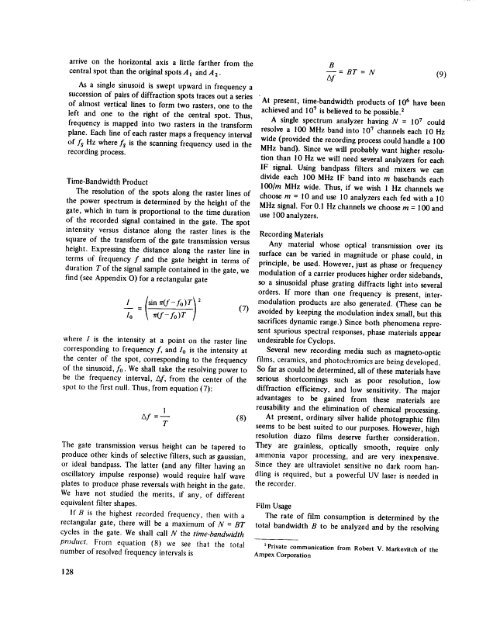
I {sinTt(f-fo)TI2<br />
7o= l<br />
where I is the intensity at a point on the raster line<br />
corresponding to frequency f, <strong>and</strong> Io is the intensity at<br />
the center <strong>of</strong> the spot, corresponding to the frequency<br />
<strong>of</strong> the sinusoid, f0. We shall take the resolving power to<br />
be the frequency interval, Af, from the center <strong>of</strong> the<br />
spot to the first null. Thus, from equation (7):<br />
(7)<br />
1<br />
Af =-- (8)<br />
T<br />
The gate transmission versus height can be tapered to<br />
produce other kinds <strong>of</strong> selective filters, such as gaussian,<br />
or ideal b<strong>and</strong>pass. The latter (<strong>and</strong> any filter having an<br />
oscillatory impulse response) would require half wave<br />
plates to produce phase reversals with height in the gate.<br />
We have not studied the merits, if any, <strong>of</strong> different<br />
equivalent filter shapes.<br />
If B is the highest recorded frequency, then with a<br />
rectangular gate, there will be a maximum <strong>of</strong> N = BT<br />
cycles in the gate. We shall call N the time-b<strong>and</strong>width<br />
product. From equation (8) we see that the total<br />
number <strong>of</strong> resolved frequency intervals is<br />
B<br />
= BT<br />
zxf<br />
--- N (9)<br />
'At present, time-b<strong>and</strong>width products <strong>of</strong> 106 have been<br />
achieved <strong>and</strong> 107 is believed to be possiblefl<br />
A single spectrum analyzer having N = 107 could<br />
resolve a 100 MHz b<strong>and</strong> into 107 channels each 10 Hz<br />
wide (provided the recording process could h<strong>and</strong>le a 100<br />
MHz b<strong>and</strong>). Since we will probably want higher resolution<br />
than 10 Hz we will need several analyzers for each<br />
IF signal. Using b<strong>and</strong>pass filters <strong>and</strong> mixers we can<br />
divide each 100 MHz IF b<strong>and</strong> into m baseb<strong>and</strong>s each<br />
lO0[m MHz wide. Thus, if we wish 1 Hz channels we<br />
choose m = 10 <strong>and</strong> use 10 analyzers each fed with a 10<br />
MHz signal. For 0.I Hz channels we choose m = 100 <strong>and</strong><br />
use 100 analyzers.<br />
Recording<br />
Materials<br />
Any material whose optical transmission over its<br />
surface can be varied in magnitude or phase could, in<br />
principle, be used. However, just as phase or frequency<br />
modulation <strong>of</strong> a carrier produces higher order sideb<strong>and</strong>s,<br />
so a sinusoidal phase grating diffracts light into several<br />
orders. If more than one frequency is present, intermodulation<br />
products are also generated. (These can be<br />
avoided by keeping the modulation index small, but this<br />
sacrifices dynamic range.) Since both phenomena represent<br />
spurious spectral responses, phase materials appear<br />
undesirable for <strong>Cyclops</strong>.<br />
Several new recording media such as magneto-optic<br />
films, ceramics, <strong>and</strong> photochromics are being developed.<br />
So far as could be determined, all <strong>of</strong> these materials have<br />
serious shortcomings such as poor resolution, low<br />
diffraction efficiency, <strong>and</strong> low sensitivity. The major<br />
advantages to be gained from these materials are<br />
reusability <strong>and</strong> the elimination <strong>of</strong> chemical processing.<br />
At present, ordinary silver halide photographic film<br />
seems to be best suited to our purposes. However, high<br />
resolution diazo films deserve further consideration.<br />
They are grainless, optically smooth, require only<br />
ammonia vapor processing, <strong>and</strong> are very inexpensive.<br />
Since they are ultraviolet sensitive no dark room h<strong>and</strong>ling<br />
is required, but a powerful UV laser is needed in<br />
the recorder.<br />
Film Usage<br />
The rate <strong>of</strong> film consumption is determined by the<br />
total b<strong>and</strong>width B to be analyzed <strong>and</strong> by the resolving<br />
2Private communication from Robert V. Markevitch <strong>of</strong> the<br />
Ampex Corporation<br />
128


