

Project Cyclops, A Design... - Department of Earth and Planetary ...
Project Cyclops, A Design... - Department of Earth and Planetary ...
Project Cyclops, A Design... - Department of Earth and Planetary ...

Create successful ePaper yourself
Turn your PDF publications into a flip-book with our unique Google optimized e-Paper software.
APPENDIXF<br />
BASE<br />
STRUCTURES<br />
AZ-EL BASE STRUCTURES<br />
The conventional az-el mount affords maximum sky<br />
coverage, but this coverage is expensive due to increased<br />
structural weight <strong>and</strong> expensive gearing <strong>and</strong>/or track <strong>and</strong><br />
wheel assemblies. Elevation rotation is generally provided<br />
by gear or chain drives <strong>and</strong> generally requires<br />
counterweighting <strong>of</strong> the dish to locate the dish center <strong>of</strong><br />
gravity on the elevation axis. The gearing on the<br />
elevation drive must provide the necessary resistance to<br />
wind torques. If the basic dish weight (including backup<br />
structure) is W, then a weight penalty <strong>of</strong> roughly 0.3W<br />
may be incurred in positioning <strong>of</strong> the center <strong>of</strong> gravity.<br />
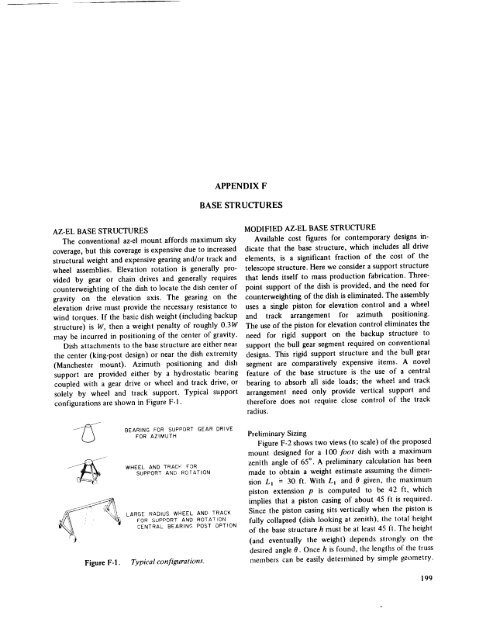
Dish attachments to the base structure are either near<br />
the center (king-post design) or near the dish extremity<br />
(Manchester mount). Azimuth positioning <strong>and</strong> dish<br />
support are provided either by a hydrostatic bearing<br />
coupled with a gear drive or wheel <strong>and</strong> track drive, or<br />
solely by wheel <strong>and</strong> track support. Typical support<br />
configurations are shown in Figure F-l.<br />
MODIFIED AZ-EL BASE STRUCTURE<br />
Available cost figures for contemporary designs indicate<br />
that the base structure, which includes all drive<br />
elements, is a significant fraction <strong>of</strong> the cost <strong>of</strong> the<br />
telescope structure. Here we consider a support structure<br />
that lends itself to mass production fabrication. Threepoint<br />
support <strong>of</strong> the dish is provided, <strong>and</strong> the need for<br />
counterweighting <strong>of</strong> the dish is eliminated. The assembly<br />
uses a single piston for elevation control <strong>and</strong> a wheel<br />
<strong>and</strong> track arrangement for azimuth positioning.<br />
The use <strong>of</strong> the piston for elevation control eliminates the<br />
need for rigid support on the backup structure to<br />
support the bull gear segment required on conventional<br />
designs. This rigid support structure <strong>and</strong> the bull gear<br />
segment are comparatively expensive items. A novel<br />
feature <strong>of</strong> the base structure is the use <strong>of</strong> a central<br />
bearing to absorb all side loads; the wheel <strong>and</strong> track<br />
arrangement need only provide vertical support <strong>and</strong><br />
therefore does not require close control <strong>of</strong> the track<br />
radius.<br />
BEARING FOR SUPPORT GEAR DRIVE<br />
FOR AZIMUTH<br />
WHEEL AND TRACK FOR<br />
SUPPORT AND ROTATION<br />
LARGE RADIUS WHEEL AND TRACK<br />
ffOR SUPPORT AND ROTATION<br />
CENTRAL BEARING POST OPTION<br />
Figure F-I. Typical configurations.<br />
Preliminary<br />
Sizing<br />
Figure F-2 shows two views (to scale) <strong>of</strong> the proposed<br />
mount designed for a I00 foot dish with a maximum<br />
zenith angle <strong>of</strong> 65 °. A preliminary calculation has been<br />
made to obtain a weight estimate assuming the dimension<br />
L_ '= 30 ft. With L_ <strong>and</strong> 0 given, the maximum<br />
piston extension p is computed to be 42 ft, which<br />
implies that a piston casing <strong>of</strong> about 45 ft is required.<br />
Since the piston casing sits vertically when the piston is<br />
fully collapsed (dish looking at zenith), the total height<br />
<strong>of</strong> the base structure h must be at least 45 ft. The height<br />
(<strong>and</strong> eventually the weight) depends strongly on the<br />
desired angle 0. Once h is found, the lengths <strong>of</strong> the truss<br />
members can be easily determined by simple geometry.<br />
199


