

Project Cyclops, A Design... - Department of Earth and Planetary ...
Project Cyclops, A Design... - Department of Earth and Planetary ...
Project Cyclops, A Design... - Department of Earth and Planetary ...

Create successful ePaper yourself
Turn your PDF publications into a flip-book with our unique Google optimized e-Paper software.
Weals<strong>of</strong>indfromequation(7)that<br />
= 2I logcos(0o/2)12<br />
r/ [sin(0 o/2)tan(0o/2)J<br />
(16)<br />
Figure 9-6 shows a plot <strong>of</strong> I/Io vs. 0 <strong>and</strong> <strong>of</strong> mf/d <strong>and</strong><br />
77vs. 0o. We see that even for values <strong>of</strong> 0o as high as 70 °,<br />
where the illumination intensity at the rim has fallen to<br />
45% <strong>of</strong> its central value, the efficiency is still almost<br />
99%. If the f/d ratio <strong>of</strong> the primary mirror is 0.25<br />
(which places the focus in the plane <strong>of</strong> the rim), <strong>and</strong> the<br />
magnification m = 3, then mf/d = 0.75 <strong>and</strong> at the<br />
Cassegrain focus 0o = 37 °. At this angle I/Io = 0.81 <strong>and</strong><br />
r/_l.<br />
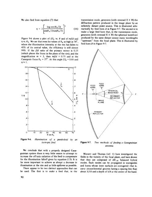
transmission mode, generates (with reversed E X H) the<br />
diffraction pattern produced in the image plane by an<br />
infinitely distant point source. This is illustrated schematically<br />
by feed horn A in Figure 9-7. The second is to<br />
make a large feed horn that, in the transmission mode,<br />
generates (with reversed E X H) the spherical wavefront<br />
produced by the same distant source many wavelengths<br />
"upstream" from the focal plane. This is illustrated by<br />
feed horn B in Figure 9-7.<br />
2.O I.O<br />
1.8 .9<br />
FEED<br />
HORN ,<br />
HORN<br />
"B"<br />
1.2<br />
fld<br />
1.0<br />
.8<br />
f<br />
d<br />
V--<br />
"A" ! _>_HERICAL<br />
_._.'" V*AVEFRONT Vl<br />
ONOARY.-<br />
,_\<br />
'\IMAGE<br />
_REFLECTOR<br />
PLANE<br />
PRIMARY /<br />
/<br />
,I<br />
i i J i<br />
IO 20 30 40<br />
0 ond 8 0<br />
'o ' o<br />
5 60 70<br />
Figure 9-6. Illumination <strong>of</strong> a<br />
isotropic<br />
feed.<br />
paraboloid by an<br />
Figure 9-7. Two methods <strong>of</strong> feeding a Cassegrainian<br />
antenna.<br />
We conclude that with a properly designed Cassegrainian<br />
system there is very little reason to attempt to<br />
increase the <strong>of</strong>f-axis radiation <strong>of</strong> the feed to compensate<br />
for the illumination fall<strong>of</strong>f given by equation (13). It is<br />
far more important to achieve as abrupt a decrease in<br />
illumination at the rim <strong>and</strong> as little spillover as possible.<br />
There appear to be two distinct approaches that can<br />
be used. The first is to make a feed that, in the<br />
Minnett <strong>and</strong> Thomas (ref. 1) have investigated the<br />
fields in the vicinity <strong>of</strong> the focal plane, <strong>and</strong> have shown<br />
that they are composed <strong>of</strong> HEwn balanced hybrid<br />
modes. Such modes can be propagated in waveguides<br />
<strong>and</strong> horns whose inner surfaces are corrugated-that is,<br />
carry circumferential grooves having a spacing less than<br />
about X/10 <strong>and</strong> a depth <strong>of</strong> X/4 at the center <strong>of</strong> the b<strong>and</strong>.<br />
92


