Project Cyclops, A Design... - Department of Earth and Planetary ...
Project Cyclops, A Design... - Department of Earth and Planetary ...
Project Cyclops, A Design... - Department of Earth and Planetary ...
You also want an ePaper? Increase the reach of your titles
YUMPU automatically turns print PDFs into web optimized ePapers that Google loves.
5. COMMUNICATION BY ELECTROMAGNETIC WAVES<br />
Having decided on electromagnetic waves as the only<br />
likely interstellar communication means, we then must<br />
ask: "Is it possible with reasonable power <strong>and</strong> antenna<br />
sizes to signal over the enormous distances involved?<br />
<strong>and</strong>: ls there an optimum region in the spectrum?" The<br />
answers to these questions involve the interplay <strong>of</strong> a<br />
number <strong>of</strong> factors that determine the performance <strong>of</strong> a<br />
communication link. In this chapter we discuss these<br />
factors as they relate to systems from radio through<br />
optical<br />
frequencies.<br />
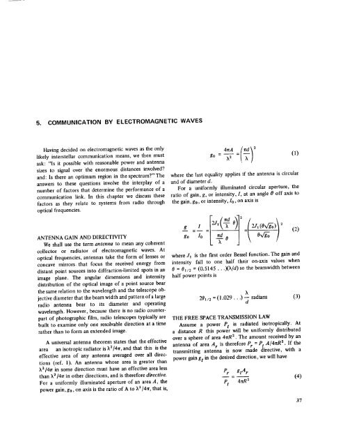
go = X2 (1)<br />
where the last equality applies if the antenna is circular<br />
<strong>and</strong> <strong>of</strong> diameter d.<br />
For a uniformly illuminated circular aperture, the<br />
ratio <strong>of</strong> gain, g, or intensity, I, at an angle 0 <strong>of</strong>f axis to<br />
the gain, go, or intensity,<br />
Io, on axis is<br />
ANTENNA GAIN AND DIRECTIVITY<br />
We shall use the term antenna to mean any coherent<br />
collector or radiator <strong>of</strong> electromagnetic waves. At<br />
optical frequencies, antennas take the form <strong>of</strong> lenses or<br />
concave mirrors that focus the received energy from<br />
distant point sources into diffraction-limited spots in an<br />
image plane. The angular dimensions <strong>and</strong> intensity<br />
distribution <strong>of</strong> the optical image <strong>of</strong> a point source bear<br />
the same relation to the wavelength <strong>and</strong> the telescope objective<br />
diameter that the beam width <strong>and</strong> pattern <strong>of</strong> a large<br />
radio antenna bear to its diameter <strong>and</strong> operating<br />
wavelength. However, because there is no radio counterpart<br />
<strong>of</strong> photographic film, radio telescopes typically are<br />
built to examine only one resolvable direction at a time<br />
rather than to form an extended image.<br />
A universal antenna theorem states that the effective<br />
area an isotropic radiator is _,2/4_r, <strong>and</strong> that this is the<br />
effective area <strong>of</strong> any antenna averaged over all directions<br />
(ref. 1). An antenna whose area is greater than<br />
3,214rr in some direction must have an effective area less<br />
than ;_2/41r in other direciions, <strong>and</strong> is therefore directive.<br />
For a uniformly illuminated aperture <strong>of</strong> an area A, the<br />
power gain, go, on axis is the ratio <strong>of</strong> A to X_]47r, that is,<br />
g=Z= ' 0<br />
go Z°<br />
)1<br />
where J! fs the first order Bessel function. The gain <strong>and</strong><br />
intensity fall to one half their on-axis values when<br />
0 = 01/2 = (0.5145 ...)(X/d) so the beamwidth between<br />
half power points is<br />
(2)<br />
X<br />
201/2 = (1.029...)<br />
--<br />
d<br />
radians (3)<br />
THE FREE SPACE TRANSMISSION LAW<br />
Assume a power Pt is radiated isotropicaUy. At<br />
a distance R this power will be uniformly distributed<br />
over a sphere <strong>of</strong> area 41rR 2. The amount received by an<br />
antenna <strong>of</strong> area A r is therefore Pr = Pt A/4nR2" If the<br />
transmitting antenna is now made directive, with a<br />
power gain gt in the desired direction, we will have<br />
Pr<br />
Pt<br />
gtAr<br />
47rR2<br />
(4)<br />
37


