

Project Cyclops, A Design... - Department of Earth and Planetary ...
Project Cyclops, A Design... - Department of Earth and Planetary ...
Project Cyclops, A Design... - Department of Earth and Planetary ...

You also want an ePaper? Increase the reach of your titles
YUMPU automatically turns print PDFs into web optimized ePapers that Google loves.
(.9<br />
Z<br />
2zr<br />
F-<br />
h.i<br />
t_ 7"/"<br />
W<br />
'I"<br />
n<br />
O<br />
TIME<br />
Figure J-2. Step approximation to ramp.<br />
0<br />
LS -IO<br />
(:3<br />
:E<br />
,:%<br />
n<br />
z<br />
,_ -30<br />
w<br />
a<br />
v -40<br />
LIJ<br />
O_<br />
-50<br />
Figure<br />
0 I<br />
J-3.<br />
l I I 1 [ I<br />
1 I t I 1__<br />
2 3 4 5 6<br />
QUANTIZATION LEVEL, n<br />
Sideb<strong>and</strong>s<br />
due to approximation.<br />
the coil current is reversed-<strong>and</strong> that the device exhibits<br />
hysteresis. For a positive frequency <strong>of</strong>fset, the phase<br />
shifter would be driven into saturation with a large<br />
negative current to ensure a stable phase condition, <strong>and</strong><br />
then to a predetermined preset point. This would take<br />
place in approximately a microsecond.<br />
The phase would then be advanced at the appropriate<br />
rate by increasing the positive current until a total<br />
excursion <strong>of</strong> 21r had occurred. The cycle would then be<br />
repeated by resetting the phase shifter as indicated by<br />
the dotted lines in Figure J-4. For negative frequency<br />
<strong>of</strong>fsets, the stable reset condition is achieved by saturating<br />
the phase shifter with a positive current.<br />
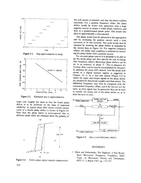
For accurate phase control it is desirable to be able to<br />
set the initial phase <strong>and</strong> then specify the rate <strong>of</strong> change<br />
(the frequency <strong>of</strong>fset). Microwave phase shifters can be<br />
set to an accuracy <strong>of</strong> about 2° . This is adequate for<br />
<strong>Cyclops</strong>. Rate control may be accomplished by frequently<br />
updating the phase shift desired, with this phase shift<br />
stored in a digital numeric register as suggested in<br />
Chapter 10, or by a true rate system (Figure J-5) in<br />
which the input <strong>and</strong> output signals at the phase shifter<br />
are sampled by directional couplers <strong>and</strong> then mixed. The<br />
difference frequency may then be compared with the<br />
comm<strong>and</strong>ed frequency <strong>of</strong>fset, <strong>and</strong> if the two are not the<br />
same, an error signal may be generated that can be used<br />
to modify the sweep rate <strong>of</strong> the phase shifter so, as to<br />
drive the error to zero.<br />
types cost roughly the same so that the' ferrite phase<br />
shifter is to be preferred on the basis <strong>of</strong> improved<br />
reliability. A typical phase shift versus control current<br />
curve <strong>of</strong> a ferrite phase shifter is shown in Figure J-4.<br />
Note that the phase shifter is nonreciprocal-that is,<br />
different phase shifts are obtained when the polarity <strong>of</strong><br />
+¢<br />
i<br />
/<br />
A(,O<br />
FROM<br />
COMPUTER<br />
-I<br />
,",@:2_<br />
L<br />
÷I i<br />
I<br />
Figure J-5. Rate controlled phase shifter.<br />
Figure .1-4.<br />
212<br />
i<br />
_- ZXI<br />
t<br />
-cb<br />
Ferrite phase shifter transfer characteristic.<br />
REFERENCE<br />
1. Klein <strong>and</strong> Dubrowsky, The Digilator, a New Broadb<strong>and</strong><br />
Microwave Frequency Translator, IEEE<br />
Trans. on Microwave Theory <strong>and</strong> Techniques,<br />
MTT-15, 3, March 1967, pp. 172-179.


