

Project Cyclops, A Design... - Department of Earth and Planetary ...
Project Cyclops, A Design... - Department of Earth and Planetary ...
Project Cyclops, A Design... - Department of Earth and Planetary ...

Create successful ePaper yourself
Turn your PDF publications into a flip-book with our unique Google optimized e-Paper software.
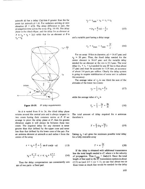
azimuth _) has a delay (2a/c)sin 0 greater than the far<br />
point (at azimuth _b+ 7r). For radiation arriving at zero<br />
elevation (0 = n/2). The delay difference is 2a/c, the<br />
propagation time across the array (Fig. 10-10). The delay<br />
plane is the tilted ellipse, <strong>and</strong> the delay for an element at<br />
A is ra = z_ + 2a/c while that tbr an element at B is<br />
T b = T_.<br />
= rmi n -7"0 = _'_ + 7"2<br />
a<br />
r<br />
= (r_ + _) (1 - _-) (15)<br />
<strong>and</strong> a variable part having a delay range<br />
T<br />
A<br />
2O<br />
rl+-- C-<br />
2r<br />
_'v = _'max - rmin = (16)<br />
¢<br />
vl<br />
For an array 10 km in diameter, ale = 16.67/asec <strong>and</strong><br />
r_ _ 20 /asec. Thus, the fixed delay needed for the<br />
center element is 36.67 /.tsec <strong>and</strong> the variable delay<br />
needed for an element at the rim is 33.3/asec. The total<br />
delay (rl + _'2 + rv) needed for any IF line is thus about<br />
37 #sec <strong>and</strong> must be accurate to -+1/8 nsec, an accuracy<br />
<strong>of</strong> about 3.4 parts per million. Clearly the delay system<br />
is going to require stabilization <strong>of</strong> some sort to achieve<br />
this accuracy.<br />
SIGNAL<br />
The average value <strong>of</strong> zf is one third the sum <strong>of</strong> the<br />
altitudes <strong>of</strong> the lower two cones:<br />
1<br />
rf =-_ (r_ +-_-ac) (17)<br />
while the average value <strong>of</strong> r v is<br />
Figure 10-10. IF delay requirements.<br />
2 2a 4a<br />
7u = 7" c - 3c (18)<br />
As 4_ is varied from 0 to 2rr, the tilted delay plane<br />
rotates around the central axis <strong>and</strong> is always tangent to<br />
two cones having their common vertex at P. If we<br />
arrange to pivot the delay plane at P, then for greater<br />
elevation angles it will always lie between these two<br />
cones. The required delay for any element is never<br />
greater than that defined by the upper cone <strong>and</strong> never<br />
less than that defined by the lower cone <strong>of</strong> the pair. For<br />
an antenna element at azimuth a <strong>and</strong> radius r from the<br />
center<br />
<strong>of</strong> the array<br />
The total amount <strong>of</strong> delay required for n antennas<br />
therefore is<br />
n 5a<br />
T = ff (r£ + "c-') (19)<br />
Taking r£ = a/c gives the minimum possible total delay<br />
for a fully steerable array<br />
r = 7"_+ a + r sin 0 cos(_ - a)<br />
e e<br />
a-r<br />
e<br />
Thus the delay compensation can conveniently consist<br />
<strong>of</strong> two parts-a<br />
fixed part<br />
a+t<br />
c<br />
_a3)<br />
2a<br />
T = n -- (20)<br />
e<br />
If the delay is obtained with additional transmission<br />
line the total length needed is vT, where v is the velocity<br />
(14) <strong>of</strong> propagation. Thus Lmi n = 2ha(v/c). Since the total<br />
length <strong>of</strong> line used in the IF transmission system is about<br />
(2/3) na (<strong>and</strong> 2/3 < vie < 1), we see that about two to<br />
three times as much line would be needed for the delay<br />
115


