- Page 1 and 2:
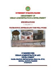
GOVERNMENT OF MADHYA PRADESH, URBAN
- Page 3 and 4:
SECTION 100
- Page 5 and 6:
101 INTRODUCTION These specificatio
- Page 7 and 8:
13.2 74 *11.2 *63 9.50 53 *8.00 *45
- Page 9 and 10:
107 CONTRACT DRAWINGS 107.1 The Con
- Page 11 and 12:
110.3 No clearance or alterations t
- Page 13 and 14:
Any vehicle with open load-carrying
- Page 15 and 16:
warning lights of similar type shal
- Page 17 and 18:
Location of the scales shall be as
- Page 19 and 20:
c) Sequence of construction and det
- Page 21 and 22:
ecording shall be done in the prese
- Page 23 and 24:
IRC : 47-1972 IRC : 48-1972 Tentati
- Page 25 and 26:
Number Designation IS:1216-1978 IS:
- Page 27 and 28:
Number Designation IS:12269-1987 IS
- Page 29 and 30:
Number Designation BS:7542 CRR I &
- Page 31 and 32:
CONTENT Clause No Description 201 S
- Page 33 and 34:
(v) All products of clearing and gr
- Page 35 and 36:
202.6. Measurements for Payment The
- Page 37 and 38:
CONTENT Clause No Description 301 E
- Page 39 and 40:
301.3 Construction Operations 301.3
- Page 41 and 42:
301.6 Preparation of Cut Formation
- Page 43 and 44:
(13) At a time, not more than 10 ch
- Page 45 and 46:
All overburden soil and weathered r
- Page 47 and 48:
If it is determined beforehand that
- Page 49 and 50:
11. Excavation in marshes shall beg
- Page 51 and 52:
Table 300-2 Compaction Requirements
- Page 53 and 54:
maintained at such a crossfall (not
- Page 55 and 56:
(c) Only the materials satisfying t
- Page 57 and 58:
4 Where the available embankment ma
- Page 59 and 60:
of drainage. 309.2 Surface Drains S
- Page 61 and 62:
Damage to the fabric resulting from
- Page 63 and 64:
CONTENT Clause No 401 GRANULAR SUB-
- Page 65 and 66:
TABLE 400-1. GRADING FOR CLOSE -GRA
- Page 67 and 68:
(iii) Compaction: Density shall be
- Page 69 and 70:
402.3.6. Addition of lime: Lime may
- Page 71 and 72:
TABLE 400 -6. PHYSICAL REQUIREMENTS
- Page 73 and 74:
The consolidated details of quantit
- Page 75 and 76:
(4) Rolling shall be discontinued w
- Page 77 and 78:
(ii) Furnishing all materials to be
- Page 79 and 80:
(4) Optimum moisture for mixing sha
- Page 81 and 82:
406.8 Measurements for Payment Wet
- Page 83 and 84:
iv) For kerb in running meters v) F
- Page 85 and 86:
409.3.4 Precast cement concrete blo
- Page 87 and 88:
The surface finish of construction
- Page 89 and 90:
CONTENT Clause No Description 501 G
- Page 91 and 92:
(k) Use of Premix seal coat:- It is
- Page 93 and 94:
Number 0 and 1 are of very low cons
- Page 95 and 96:
area beyond it, shall be laid by ha
- Page 97 and 98:
501.8. Preparation of Surface 501.8
- Page 99 and 100:
Normally, the maximum layer thickne
- Page 101 and 102:
5. 6. Bituminous penetration macada
- Page 103 and 104:
Control of temperature of binder in
- Page 105 and 106:
501.8.7.5 Tack coat: This is to be
- Page 107 and 108:
6. Emergency Response 6.1. The Cont
- Page 109 and 110:
carpet to ensure a proper bond betw
- Page 111 and 112:
504.2.2. Coarse aggregates: (i)The
- Page 113 and 114:
504.8. Rate The cont react unit rat
- Page 115 and 116:
505.7. Measurement for Payment Pene
- Page 117 and 118:
The contract unit rate for built-up
- Page 119 and 120:
507.3. Mixture Design 507.3.1. Requ
- Page 121 and 122:
507.4. Construction Operations 507.
- Page 123 and 124:
1. IS: 2386 Part 1 2. IS: 2386 Part
- Page 125 and 126:
508.8. Measurement for Payment The
- Page 127 and 128:
Notes: 1. The combined aggregate gr
- Page 129 and 130:
ase, followed by a cover of stone c
- Page 131 and 132:
The equipment and general procedure
- Page 133 and 134:
Aggregates (a) Nominal Stone size 1
- Page 135 and 136:
(A) Premix Carpet (a) Coarse aggreg
- Page 137 and 138:
511.2.6. Surface finish and quality
- Page 139 and 140:
(i)The stone chips shall consist of
- Page 141 and 142:
S. No. Nominal size of aggregate De
- Page 143 and 144:
* In cold climatic regions (tempera
- Page 145 and 146:
(vi)During cooking and mixing, care
- Page 147 and 148:
(i)It is usual to use ordinary Port
- Page 149 and 150:
(iii)The Contractor shall monitor t
- Page 151 and 152:
519.2.1.3. Aggregate grading and bi
- Page 153 and 154:
evaporation of water and/or solvent
- Page 155 and 156:
519.3.1.3 Aggregate grading and bin
- Page 157 and 158:
519.3.6. Measurement for payment: R
- Page 159 and 160:
Loss in Weight, %., Maximum Increas
- Page 161 and 162:
522.2. Materials 522.2.1. Binder: B
- Page 164 and 165:
600 Concrete Pavements
- Page 166 and 167:
601. DRY LEAN CEMENT CONCRETE SUB-B
- Page 168 and 169:
601.4. Subgrade The subgrade shall
- Page 170 and 171:
601.5.7. Curing: As soon as the lea
- Page 172 and 173:
602.2. Materials 602.2.1. Source of
- Page 174 and 175:
602.3.2. Cement content: The cement
- Page 176 and 177:
602.6.2.2. Contraction joints: Cont
- Page 178 and 179:
602.6.6. Tie bars 602.6.6.1. Tie ba
- Page 180 and 181:
602.9.3.2. Batching plant and equip
- Page 182 and 183:
602.9.5.2. The concrete shall be di
- Page 184 and 185:
mechanical sprayer shall incorporat
- Page 186 and 187:
after concrete has set to expose do
- Page 188 and 189:
joints is completed including the c
- Page 190 and 191:
603.2.3.4. The coarse and fine aggr
- Page 192:
603.9. Tolerances for Surface Regul
- Page 195 and 196:
701 GEOSYNTHETICS IN ROAD AND BRIDG
- Page 197 and 198:
Table 700-2 Geotextile Requirements
- Page 199 and 200:
strong acid/bases, flames including
- Page 201 and 202:
702.4 Measurement for Payment The g
- Page 203 and 204:
dimensional stability relative to e
- Page 205 and 206:
706 GEOSYNTHETICS FOR HIGHWAY PAVEM
- Page 207 and 208:
707.2.3 Tack coat: The tack coat us
- Page 209 and 210:
708.3.2 Construction and installati
- Page 211 and 212:
CONTENT Clause No Description 801 T
- Page 213 and 214:
801.3.1. General requirements: The
- Page 215 and 216:
lack free adhesive activated by hea
- Page 217 and 218:
(iii) (iv) (v) (vi) (vii) (viii) (i
- Page 219 and 220:
802.1.1. Overhead signs may be used
- Page 221 and 222:
802.7.6. Before erecting support st
- Page 223 and 224:
(c) Skid resistance : not less than
- Page 225 and 226:
(b) The marking shall not lift from
- Page 227 and 228:
The work covers supplying and fixin
- Page 229 and 230:
809.3.1. The location of crash barr
- Page 231:
810.7.3. No measurement for payment
- Page 234 and 235:
901. GENERAL 901.1. All materials t
- Page 236 and 237:
902.3. Surface Levels The levels of
- Page 238 and 239:
eplacement of a bituminous layer is
- Page 240 and 241:
per 5 tones 3. Water Bound Macadam
- Page 243 and 244:
CONTENT Clause No Description 1001
- Page 245 and 246:
ecommended threshold values as per
- Page 247 and 248:
S 415 IS:17B6 High Yield 415 200 St
- Page 249 and 250:
and testing of concrete. The contra
- Page 251 and 252:
prevented. The use of correctly for
- Page 254 and 255:
CONTENT Clause No Description 1101
- Page 256 and 257:
1105. TEST PILES 1105.1. Test piles
- Page 258 and 259:
The concrete shall be properly grad
- Page 260 and 261:
During driving the top of pile shal
- Page 262 and 263:
concrete in the installed pile and
- Page 264:
the head to the butt of the shoe or
- Page 267 and 268:
1201. DESCRIPTION This work consist
- Page 269 and 270:
1205. WELL CURB 1205.1. The well cu
- Page 271 and 272:
Separate high pressure connection f
- Page 273 and 274:
Care shall be taken to keep all par
- Page 275 and 276:
The well shall be uniformly seated
- Page 277 and 278:
d) The Contract unit rates for sand
- Page 279 and 280:
CONTENT Clause No 1301 DESCRIPTION
- Page 281 and 282:
Such soaked bricks shall be stacked
- Page 283 and 284:
The surfaces can be finished by "jo
- Page 285 and 286:
In case of plaster finish, the mini
- Page 287 and 288:
CONTENT Clause No Description 1401
- Page 289 and 290:
e fluid mixed thoroughly and then p
- Page 291 and 292:
1405.3.5. Quoin stone : Quoin stone
- Page 293 and 294:
1405.9. Wee Holes Weep holes shall
- Page 295 and 296:
CONTENT Clause No Description 1501
- Page 297 and 298:
1504.6. Shuttering for walls, slopi
- Page 299 and 300:
When formwork is dismantled, its in
- Page 301 and 302:
CONTENT Clause No Description 1601
- Page 303 and 304:
(i) In case of beam and slab constr
- Page 305 and 306:
(iii)The fabrication, furnishing an
- Page 307 and 308:
CONTENT Clause No Description 1701
- Page 309 and 310:
TABLE 1700-3. FOR BRIDGES OTHER THA
- Page 311 and 312:
(iii)The initial trial mixes shall
- Page 313 and 314:
Unless specified otherwise, equipme
- Page 315 and 316:
All under water concreting shall be
- Page 317 and 318:
disappears. The second application
- Page 319 and 320:
(iv) After the passage of the above
- Page 321 and 322:
CONTENT Clause No Description 1801
- Page 323 and 324:
1802.2.3. In severe environment, ca
- Page 325 and 326:
strength of steel to concrete. Grou
- Page 327 and 328:
) If the calculated elongation has
- Page 329 and 330:
1809.5. Protection of Ends The expo
- Page 331 and 332: 1900 Structural Steel
- Page 333 and 334: 1901. DESCRIPTION This work shall i
- Page 335 and 336: All work shall be in accordance wit
- Page 337 and 338: 1904.3.2. Block drilling : Where th
- Page 339 and 340: Taper washers with correct angle of
- Page 341 and 342: Welding shall not be done when the
- Page 343 and 344: column. This dimension shall be mea
- Page 345 and 346: IS:7969 dealing with handling of ma
- Page 347 and 348: (i) (ii) (iii) iv) Visual Inspectio
- Page 349 and 350: (ii) Chemical Resistant Paints The
- Page 351 and 352: Two coats of aluminum paint conform
- Page 353: Weight of structural secti ons shal
- Page 356 and 357: 2001. DESCRIPTION This work shall c
- Page 358 and 359: Tolerances on height of any compone
- Page 360 and 361: A bottom plate with concave surface
- Page 362 and 363: 3.1 Max change in Hardness IRHD +15
- Page 364 and 365: The size and composition of accepta
- Page 366 and 367: 1. Acceptance testing by an indepen
- Page 368 and 369: ii) Template of 6 mm M.S. plate and
- Page 370 and 371: ix) Pot bearings including all pans
- Page 372 and 373: ii) Overall height : -0 to +3 mm ii
- Page 374 and 375: 2008. TESTS AND STANDARDS OF ACCEPT
- Page 376 and 377: CONTENT Clause No Description 2101
- Page 378 and 379: Formwork and concrete shall conform
- Page 380 and 381: CONTENT Clause No Description 2201
- Page 384 and 385: CONTENT Clause No Description 2301
- Page 386 and 387: The surface finish of the deck slab
- Page 388 and 389: 2400 Surface and Sub-surface Geotec
- Page 390 and 391: 2401. GENERAL 2401.1. The objective
- Page 392 and 393: 2403.5. Logging of bore-holes by ra
- Page 394 and 395: For preliminary and detailed sub-su
- Page 396 and 397: 2408.4. Rock Samples 2408.4.1. Dist
- Page 398 and 399: 1. (a) During construction or immed
- Page 400 and 401: 2500 River Training Work and Protec
- Page 402 and 403: 2501 DESCRIPTION River training and
- Page 404 and 405: Wherever possible, crates shall be
- Page 406 and 407: 2505. RUBBLE STONE/CEMENT CONCRETE
- Page 408 and 409: 2600 Expansion Joints
- Page 410 and 411: 2601. DESCRIPTION This work shall c
- Page 412 and 413: 2603.4. Performance Requirement wit
- Page 414 and 415: 2606. ELASTOMERIC SLAB SEAL EXPANSI
- Page 416 and 417: iii) While removing the spacer bar
- Page 418 and 419: ix) All excess sealant shall be rem
- Page 420 and 421: TABLE 2600-1. STRIP SEAL ELEMENT SP
- Page 422 and 423: iii) In view of the importance of t
- Page 424 and 425: 2700 Wearing Coat and Appurtenances
- Page 426 and 427: 2701. DESCRIPTION This work shall i
- Page 428 and 429: deck structure. In case of viaducts
- Page 430 and 431: 2800 Repair of Structures
- Page 432 and 433:
2801. DESCRIPTION Repair of structu
- Page 434 and 435:
ecommendations. When mined, all adh
- Page 436 and 437:
Bond Strength : 12 MPa Tensile Stre
- Page 438 and 439:
Grouting shall normally be performe
- Page 440 and 441:
2807.11. Sufficient clearance shall
- Page 442 and 443:
The behaviour of the girder shall b
- Page 444 and 445:
CONTENT Clause No Description 2901
- Page 446 and 447:
suffer any undue structural strain,
- Page 448 and 449:
3000 Maintenance of Road
- Page 450 and 451:
3001. GENERAL The Specifications sh
- Page 452 and 453:
3004.1.5. Measurements for payment: