

This section is available on request - MAN Diesel & Turbo
This section is available on request - MAN Diesel & Turbo
This section is available on request - MAN Diesel & Turbo

Create successful ePaper yourself
Turn your PDF publications into a flip-book with our unique Google optimized e-Paper software.
<strong>MAN</strong> B&W 1.06<br />
From the accumulator, the gas passes through<br />
a bore in the valve block to the shut down valve,<br />
which in the gas mode, <str<strong>on</strong>g>is</str<strong>on</strong>g> kept open by compressed<br />
air. From the shutdown valve (V4 in Fig.<br />
7.00.0 ), the gas <str<strong>on</strong>g>is</str<strong>on</strong>g> led to the gas injecti<strong>on</strong> valve<br />
via bores in the valve block and in the cylinder<br />
cover. A blow�off valve (V in Fig. 7.00.0 ), placed<br />
<strong>on</strong> the valve block, <str<strong>on</strong>g>is</str<strong>on</strong>g> designed to empty the gas<br />
bores when needed.<br />
A purge valve (V5 shown in Fig. 7.00.0 ), which<br />
<str<strong>on</strong>g>is</str<strong>on</strong>g> also placed <strong>on</strong> the valve block, <str<strong>on</strong>g>is</str<strong>on</strong>g> designed to<br />
empty the accumulator when the engine <str<strong>on</strong>g>is</str<strong>on</strong>g> no<br />
l<strong>on</strong>ger to operate in the gas mode.<br />
Fuel Valves, Gas Valves and<br />
Starting Air Valve<br />
The cylinder cover <str<strong>on</strong>g>is</str<strong>on</strong>g> equipped with two or three fuel<br />
oil valves, two or three gas valves, starting air valve,<br />
and indicator cock.<br />
The opening of the fuel valves <str<strong>on</strong>g>is</str<strong>on</strong>g> c<strong>on</strong>trolled by the<br />
high pressure fuel oil created by the fuel oil pressure<br />
booster, and the valves are closed by a spring.<br />
The opening of the gas valve <str<strong>on</strong>g>is</str<strong>on</strong>g> c<strong>on</strong>trolled by the<br />
ELGI valve, which operates <strong>on</strong> c<strong>on</strong>trol oil taken from<br />
the system oil.<br />
An automatic vent slide allows circulati<strong>on</strong> of fuel<br />
oil through the valve and high pressure pipes when<br />
the engine <str<strong>on</strong>g>is</str<strong>on</strong>g> stopped. The vent slide also prevents<br />
the compressi<strong>on</strong> chamber from being filled up with<br />
fuel oil in the event that the valve spindle sticks. Oil<br />
from the vent slide and other drains <str<strong>on</strong>g>is</str<strong>on</strong>g> led away in<br />
a closed system.<br />
The fuel oil high�pressure pipes are equipped with<br />
protective hoses and are neither heated nor insulated.<br />
The mechanically driven starting air d<str<strong>on</strong>g>is</str<strong>on</strong>g>tributor used<br />
<strong>on</strong> the MC engines has been replaced by <strong>on</strong>e solenoid<br />
valve per cylinder, c<strong>on</strong>trolled by the CCUs of<br />
the Engine C<strong>on</strong>trol System.<br />
Slow turning before starting <str<strong>on</strong>g>is</str<strong>on</strong>g> a program incorporated<br />
into the basic Engine C<strong>on</strong>trol System.<br />
Page 5 of 8<br />
The starting air system <str<strong>on</strong>g>is</str<strong>on</strong>g> described in detail in Secti<strong>on</strong><br />
.0 .<br />
The starting valve <str<strong>on</strong>g>is</str<strong>on</strong>g> opened by c<strong>on</strong>trol air and <str<strong>on</strong>g>is</str<strong>on</strong>g><br />
closed by a spring. The integrated Engine C<strong>on</strong>trol<br />
System c<strong>on</strong>trols the starting valve timing.<br />
Fuel injecti<strong>on</strong> valves<br />
Dual fuel operati<strong>on</strong> requires valves for both the injecti<strong>on</strong><br />
of fuel oil (incl. pilot oil) and gas fuel.<br />
The valves are of separate types, and two are fitted<br />
for gas injecti<strong>on</strong> and two for fuel oil. The media<br />
required for both fuel and gas operati<strong>on</strong> <str<strong>on</strong>g>is</str<strong>on</strong>g> shown<br />
below:<br />
• High�pressure gas supply<br />
• Fuel oil supply (pilot oil)<br />
• C<strong>on</strong>trol oil supply for activati<strong>on</strong> of gas injecti<strong>on</strong><br />
valves<br />
• Sealing oil supply.<br />
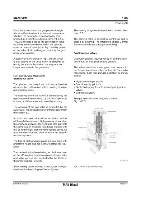
The gas injecti<strong>on</strong> valve design <str<strong>on</strong>g>is</str<strong>on</strong>g> shown in<br />
Fig. .06.0 .<br />
��������������<br />
�����������������<br />
�����������������<br />
������������������<br />
����������������������<br />
�����������<br />
�����������<br />
�����������<br />
<strong>MAN</strong> B&W ME-GI engines 198 50 59-7.1<br />
<strong>MAN</strong> <strong>Diesel</strong><br />
���������<br />
Fig. 1.06.01: Gas injecti<strong>on</strong> valve<br />
178 53 64�5.0


