

This section is available on request - MAN Diesel & Turbo
This section is available on request - MAN Diesel & Turbo
This section is available on request - MAN Diesel & Turbo

You also want an ePaper? Increase the reach of your titles
YUMPU automatically turns print PDFs into web optimized ePapers that Google loves.
<strong>MAN</strong> B&W 2.04<br />
Engine Layout and Load Diagram<br />
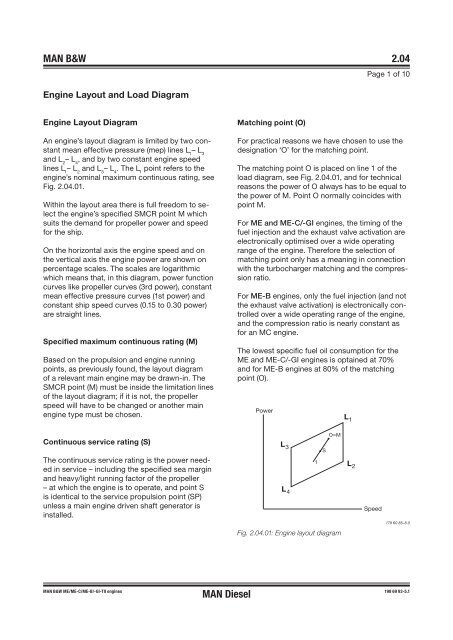
Engine Layout Diagram<br />
An engine’s layout diagram <str<strong>on</strong>g>is</str<strong>on</strong>g> limited by two c<strong>on</strong>stant<br />
mean effective pressure (mep) lines L 1 – L 3<br />
and L 2 – L 4 , and by two c<strong>on</strong>stant engine speed<br />
lines L 1 – L 2 and L 3 – L 4 . The L 1 point refers to the<br />
engine’s nominal maximum c<strong>on</strong>tinuous rating, see<br />
Fig. 2.04.01.<br />
Within the layout area there <str<strong>on</strong>g>is</str<strong>on</strong>g> full freedom to select<br />
the engine’s specified SMCR point M which<br />
suits the demand for propeller power and speed<br />
for the ship.<br />
On the horiz<strong>on</strong>tal ax<str<strong>on</strong>g>is</str<strong>on</strong>g> the engine speed and <strong>on</strong><br />
the vertical ax<str<strong>on</strong>g>is</str<strong>on</strong>g> the engine power are shown <strong>on</strong><br />
percentage scales. The scales are logarithmic<br />
which means that, in th<str<strong>on</strong>g>is</str<strong>on</strong>g> diagram, power functi<strong>on</strong><br />
curves like propeller curves (3rd power), c<strong>on</strong>stant<br />
mean effective pressure curves (1st power) and<br />
c<strong>on</strong>stant ship speed curves (0.15 to 0.30 power)<br />
are straight lines.<br />
Specified maximum c<strong>on</strong>tinuous rating (M)<br />
Based <strong>on</strong> the propulsi<strong>on</strong> and engine running<br />
points, as previously found, the layout diagram<br />
of a relevant main engine may be drawn�in. The<br />
SMCR point (M) must be inside the limitati<strong>on</strong> lines<br />
of the layout diagram; if it <str<strong>on</strong>g>is</str<strong>on</strong>g> not, the propeller<br />
speed will have to be changed or another main<br />
engine type must be chosen.<br />
C<strong>on</strong>tinuous service rating (S)<br />
The c<strong>on</strong>tinuous service rating <str<strong>on</strong>g>is</str<strong>on</strong>g> the power needed<br />
in service – including the specified sea margin<br />
and heavy/light running factor of the propeller<br />
– at which the engine <str<strong>on</strong>g>is</str<strong>on</strong>g> to operate, and point S<br />
<str<strong>on</strong>g>is</str<strong>on</strong>g> identical to the service propulsi<strong>on</strong> point (SP)<br />
unless a main engine driven shaft generator <str<strong>on</strong>g>is</str<strong>on</strong>g><br />
installed.<br />
<strong>MAN</strong> B&W ME/ME-C/ME-B/-GI-TII engines<br />
<strong>MAN</strong> <strong>Diesel</strong><br />
Matching point (O)<br />
Page 1 of 10<br />
For practical reas<strong>on</strong>s we have chosen to use the<br />
designati<strong>on</strong> ‘O’ for the matching point.<br />
The matching point O <str<strong>on</strong>g>is</str<strong>on</strong>g> placed <strong>on</strong> line 1 of the<br />
load diagram, see Fig. 2.04.01, and for technical<br />
reas<strong>on</strong>s the power of O always has to be equal to<br />
the power of M. Point O normally coincides with<br />
point M.<br />
For ME and ME-C/-GI engines, the timing of the<br />
fuel injecti<strong>on</strong> and the exhaust valve activati<strong>on</strong> are<br />
electr<strong>on</strong>ically optim<str<strong>on</strong>g>is</str<strong>on</strong>g>ed over a wide operating<br />
range of the engine. Therefore the selecti<strong>on</strong> of<br />
matching point <strong>on</strong>ly has a meaning in c<strong>on</strong>necti<strong>on</strong><br />
with the turbocharger matching and the compressi<strong>on</strong><br />
ratio.<br />
For ME-B engines, <strong>on</strong>ly the fuel injecti<strong>on</strong> (and not<br />
the exhaust valve activati<strong>on</strong>) <str<strong>on</strong>g>is</str<strong>on</strong>g> electr<strong>on</strong>ically c<strong>on</strong>trolled<br />
over a wide operating range of the engine,<br />
and the compressi<strong>on</strong> ratio <str<strong>on</strong>g>is</str<strong>on</strong>g> nearly c<strong>on</strong>stant as<br />
for an MC engine.<br />
The lowest specific fuel oil c<strong>on</strong>sumpti<strong>on</strong> for the<br />
ME and ME-C/-GI engines <str<strong>on</strong>g>is</str<strong>on</strong>g> optained at 70%<br />
and for ME-B engines at 80% of the matching<br />
point (O).<br />
Power<br />
L 3<br />
L 4<br />
O=M<br />
Fig. 2.04.01: Engine layout diagram<br />
1<br />
S<br />
L 1<br />
L 2<br />
Speed<br />
178 60 85-8.0<br />
198 69 93-5.1


