

This section is available on request - MAN Diesel & Turbo
This section is available on request - MAN Diesel & Turbo
This section is available on request - MAN Diesel & Turbo

Create successful ePaper yourself
Turn your PDF publications into a flip-book with our unique Google optimized e-Paper software.
<strong>MAN</strong> B&W 2.04<br />
Engine Load Diagram<br />
Definiti<strong>on</strong>s<br />
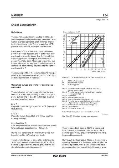
The engine’s load diagram, see Fig. 2.04.02, defines<br />
the power and speed limits for c<strong>on</strong>tinuous as<br />
well as overload operati<strong>on</strong> of an installed engine<br />
having a matching point O and a specified MCR<br />
point M that c<strong>on</strong>firms the ship’s specificati<strong>on</strong>.<br />
Point A <str<strong>on</strong>g>is</str<strong>on</strong>g> a 100% speed and power reference<br />
point of the load diagram, and <str<strong>on</strong>g>is</str<strong>on</strong>g> defined as the<br />
point <strong>on</strong> the propeller curve (line 1), through the<br />
matching point O, having the specified MCR<br />
power. Normally, point M <str<strong>on</strong>g>is</str<strong>on</strong>g> equal to point A, but<br />
in special cases, for example if a shaft generator<br />
<str<strong>on</strong>g>is</str<strong>on</strong>g> installed, point M may be placed to the right of<br />
point A <strong>on</strong> line 7.<br />
The service points of the installed engine incorporate<br />
the engine power required for ship propulsi<strong>on</strong><br />
and shaft generator, if installed.<br />
Operating curves and limits for c<strong>on</strong>tinuous<br />
operati<strong>on</strong><br />
The c<strong>on</strong>tinuous service range <str<strong>on</strong>g>is</str<strong>on</strong>g> limited by four<br />
lines: 4, 5, 7 and 3 (9), see Fig. 2.04.02. The propeller<br />
curves, line 1, 2 and 6 in the load diagram<br />
are also described below.<br />
Line 1:<br />
Propeller curve through specified MCR (M) engine<br />
layout curve.<br />
Line 2:<br />
Propeller curve, fouled hull and heavy weather<br />
– heavy running.<br />
Line 3 and line 9:<br />
Line 3 represents the maximum acceptable speed<br />
for c<strong>on</strong>tinuous operati<strong>on</strong>, i.e. 105% of A.<br />
During trial c<strong>on</strong>diti<strong>on</strong>s the maximum speed may<br />
be extended to 107% of A, see line 9.<br />
The above limits may in general be extended to<br />
105% and during trial c<strong>on</strong>diti<strong>on</strong>s to 107% of the<br />
nominal L 1 speed of the engine, provided the torsi<strong>on</strong>al<br />
vibrati<strong>on</strong> c<strong>on</strong>diti<strong>on</strong>s permit.<br />
<strong>MAN</strong> B&W ME/ME-C/ME-B/-GI-TII engines<br />
<strong>MAN</strong> <strong>Diesel</strong><br />
Engine shaft power, % of A<br />
110<br />
105<br />
100<br />
95<br />
90<br />
85<br />
80<br />
75<br />
70<br />
65<br />
60<br />
55<br />
50<br />
45<br />
7<br />
5<br />
4<br />
1 2 6<br />
8 4 1<br />
2<br />
Page 2 of 10<br />
O=A=M<br />
7<br />
5<br />
40<br />
60 65 70 75 80 85 90 95 100 105 110<br />
6<br />
Engine speed, % of A<br />
Regarding ‘i’ in the power functi<strong>on</strong> P = c x n i , see page 2.01.<br />
A 100% reference point<br />
M Specified MCR point<br />
O Matching point<br />
Line 1 Propeller curve through matching point (i = 3)<br />
(engine layout curve)<br />
Line 2 Propeller curve, fouled hull and heavy weather<br />
– heavy running (i = 3)<br />
Line 3 Speed limit<br />
Line 4 Torque/speed limit (i = 2)<br />
Line 5 Mean effective pressure limit (i = 1)<br />
Line 6 Propeller curve, clean hull and calm weather<br />
– light running (i = 3), for propeller layout<br />
Line 7 Power limit for c<strong>on</strong>tinuous running (i = 0)<br />
Line 8 Overload limit<br />
Line 9 Speed limit at sea trial<br />
Point M to be located <strong>on</strong> line 7 (normally in point A)<br />
Fig. 2.04.02: Standard engine load diagram<br />
The overspeed set�point <str<strong>on</strong>g>is</str<strong>on</strong>g> 109% of the speed<br />
in A, however, it may be moved to 109% of the<br />
nominal speed in L 1 , provided that torsi<strong>on</strong>al vibrati<strong>on</strong><br />
c<strong>on</strong>diti<strong>on</strong>s permit.<br />
Running at low load above 100% of the nominal L 1<br />
speed of the engine <str<strong>on</strong>g>is</str<strong>on</strong>g>, however, to be avoided for<br />
extended periods. Only plants with c<strong>on</strong>trollable<br />
pitch propellers can reach th<str<strong>on</strong>g>is</str<strong>on</strong>g> light running area.<br />
3<br />
9<br />
178 05 42�7.5<br />
198 69 93-5.1


