

1938 LaSalle Production - GM Heritage Center
1938 LaSalle Production - GM Heritage Center
1938 LaSalle Production - GM Heritage Center

Create successful ePaper yourself
Turn your PDF publications into a flip-book with our unique Google optimized e-Paper software.
Cadillac-LaSaile Preliminary Service Information 17<br />
to which the rods from the control shafts are<br />
attached; while on the inner end a shoe on an inner<br />
lever contacts the high and intermediate<br />
shifter disc, and the shoe on the other lever shifts<br />
the low and reverse sliding gear.<br />
Inasmuch as shifter shafts are not employed with<br />
this construction, the shifter locking balls operate<br />
against notched quadrants on the inner shifting<br />
levers as shown in Fig. 17. The locking ball pin<br />
and spring are carried in a drilled passage in the<br />
transmission case; the ball for the low and reverse<br />
lever is carried at one end of the spring and the ball<br />
for the high and intermediate lever at the other.<br />
Fulcrum Point<br />
Lug for IniK- Shaft 4 • .-.V^<br />
Hi,hand 5" d l J^V,.w<br />
Gears {^V"^- " 1 *<br />
Luy for Outer Tuba<br />
Low .11)--1 Re^'r^ C<br />
Cro^s-over<br />
Spring<br />
SU:enn„, Sli Jft<br />
• hiftun] L«rwi<br />
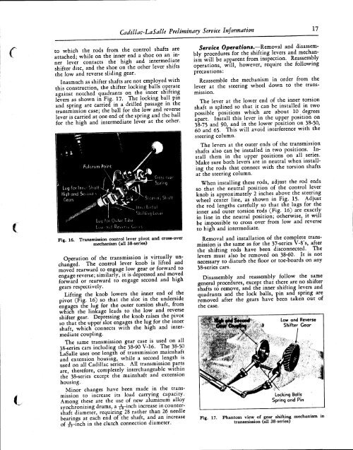
Fig. 16. Transmission control lever pivot and cross-over<br />
mechanism (all 38-series)<br />
Operation of the transmission is virtually unchanged.<br />
The control lever knob is lifted and<br />
moved rearward to engage low gear or forward to<br />
engage reverse; similarly, it is depressed and moved<br />
forward or rearward to engage second and high<br />
gears respectively.<br />
Lifting the knob lowers the inner end of the<br />
pivot (Fig. 16) so that the slot in the underside<br />
engages the lug for the outer torsion shaft, from<br />
which the linkage leads to the low and reverse<br />
shifter gear. Depressing the knob raises the pivot<br />
so that the upper slot engages the lug for the inner<br />
shaft, which connects with the high and intermediate<br />
coupling.<br />
The same transmission gear case is used on all<br />
38-series cars including the 38-90 V-16. The 38-50<br />
<strong>LaSalle</strong> uses one length of transmission mainshaft<br />
and extension housing, while a second length is<br />
used on all Cadillac series. AH transmission parts<br />
are, therefore, completely interchangeable within<br />
the 38-series except the mainshaft and extension<br />
housing.<br />
Minor changes have been made in the transmission<br />
to increase its load carrying capacity.<br />
Among these are the use of new aluminum alloy<br />
synchronizing drums, a j^-inch increase in countershaft<br />
diameter, requiring 28 rather than 26 needle<br />
bearings at each end of the shaft, and an increase<br />
of ^-inch in the clutch connection diameter.<br />
Service Operations.—Removal and disassembly<br />
procedures for the shifting levers and mechanism<br />
will be apparent from inspection. Reassembly<br />
operations, will, however, require the following<br />
precautions:<br />
Reassemble the mechanism in order from the<br />
lever at the steering wheel down to the transmission.<br />
The lever at the lower end of the inner torsion<br />
shaft is splined so that it can be installed in two<br />
possible positions which are about 10 degrees<br />
apart. Install this lever in the upper position on<br />
38-75 and 90, and in the lower position on 38-50,<br />
60 and 65. This will avoid interference with the<br />
steering column.<br />
The levers at the outer ends of the transmission<br />
shafts also can be installed in two positions. Install<br />
them in the upper positions on all series.<br />
Make sure both levers are in neutral when installing<br />
the rods that connect with the torsion shafts<br />
at the steering column.<br />
When installing these rods, adjust the rod ends<br />
so that the neutral position of the control lever<br />
knob is approximately 2 inches above the steering<br />
wheel center line, as shown in Fig. 15. Adjust<br />
the rod lengths carefully so that the lugs for the<br />
inner and outer torsion rods (Fig. 16) are exactly<br />
in line in the neutral position; otherwise, it will<br />
be impossible to cross over from low and reverse<br />
to high and intermediate.<br />
Removal and installation of the complete transmission<br />
is the same as for the 37-series V-8's, after<br />
the shifting rods have been disconnected. The<br />
levers must also be removed on 38-60. It is not<br />
necessary to disturb the floor or toe-boards on any<br />
38-series cars.<br />
Disassembly and reassembly follow the same<br />
general procedures, except that there are no shifter<br />
shafts to remove, and the inner shifting levers and<br />
quadrants and the lock balls, pin and spring arc<br />
removed after the gears have been taken out of<br />
the case.<br />
Fig. 17.<br />
Low and Reverse<br />
Shifter Gear<br />
Locking Balls<br />
Spring and Pin<br />
Phantom view of gear shifting mechanism in<br />
transmission (all 38-series)


