PPKE ITK PhD and MPhil Thesis Classes
PPKE ITK PhD and MPhil Thesis Classes
PPKE ITK PhD and MPhil Thesis Classes

Create successful ePaper yourself
Turn your PDF publications into a flip-book with our unique Google optimized e-Paper software.
3.4 Properties of the Arithmetic Units on FPGA 75<br />
1E-01<br />
1E-02<br />
Error<br />
1E-03<br />
1E-04<br />
1E-05<br />
29 30 31 32 33 35 36 37 38 39 40<br />
Arithmetic precision<br />
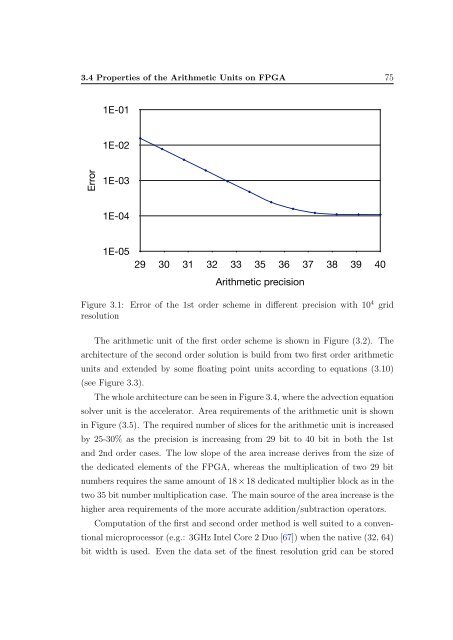
Figure 3.1: Error of the 1st order scheme in different precision with 10 4 grid<br />
resolution<br />
The arithmetic unit of the first order scheme is shown in Figure (3.2). The<br />
architecture of the second order solution is build from two first order arithmetic<br />
units <strong>and</strong> extended by some floating point units according to equations (3.10)<br />
(see Figure 3.3).<br />
The whole architecture can be seen in Figure 3.4, where the advection equation<br />
solver unit is the accelerator. Area requirements of the arithmetic unit is shown<br />
in Figure (3.5). The required number of slices for the arithmetic unit is increased<br />
by 25-30% as the precision is increasing from 29 bit to 40 bit in both the 1st<br />
<strong>and</strong> 2nd order cases. The low slope of the area increase derives from the size of<br />
the dedicated elements of the FPGA, whereas the multiplication of two 29 bit<br />
numbers requires the same amount of 18 × 18 dedicated multiplier block as in the<br />
two 35 bit number multiplication case. The main source of the area increase is the<br />
higher area requirements of the more accurate addition/subtraction operators.<br />
Computation of the first <strong>and</strong> second order method is well suited to a conventional<br />
microprocessor (e.g.: 3GHz Intel Core 2 Duo [67]) when the native (32, 64)<br />
bit width is used. Even the data set of the finest resolution grid can be stored


![optika tervezés [Kompatibilitási mód] - Ez itt...](https://img.yumpu.com/45881475/1/190x146/optika-tervezacs-kompatibilitasi-mad-ez-itt.jpg?quality=85)