

Download Full Issue in PDF - Academy Publisher
Download Full Issue in PDF - Academy Publisher
Download Full Issue in PDF - Academy Publisher

Create successful ePaper yourself
Turn your PDF publications into a flip-book with our unique Google optimized e-Paper software.
1482 JOURNAL OF COMPUTERS, VOL. 8, NO. 6, JUNE 2013<br />
t<br />
0<br />
time very far from the t time, t 0<br />
→∞, x( t− t0<br />
) has<br />
no effect on yt (); means that the predicted value of yt ()<br />
is irrelevant to x( t− t0<br />
).<br />
In the prediction of chaos traffic flow chaotic time<br />
series, t′ = t+ ( m− 1) τ , T ( T > 0 ) is forward prediction<br />
step, x( t′ + T)<br />
represents the output associated with the<br />
<strong>in</strong>put signal x()<br />
t and the delay time τ , then<br />
N l −1<br />
1<br />
l1 l<br />
<br />
2 N li 0 ∑ 1 1 1<br />
l1<br />
= 0<br />
x( t′ + T) = f( x , x , x ) = h + h ( l ) x( t−lτ<br />
)<br />
Nl<br />
−1N<br />
1<br />
2 l −<br />
2<br />
∑∑<br />
+ h ( l , l ) x( t−lτ<br />
) x( t−l<br />
τ )<br />
l1= 0 l2=<br />
0<br />
2 1 2 1 2<br />
Nl −1N 3 l −1N<br />
1<br />
3 l −<br />
3<br />
∑∑∑ h3( l1, l2, l3) xt ( l1τ) xt ( l2τ) xt ( l3τ)<br />
(5)<br />
l1= 0 l2= 0 l3=<br />
0<br />
+ − − − +<br />
note<br />
Nmax = max( N , N , N , N ) , ( i = 1, 2, 3, ),<br />
when n≥<br />
N<br />
li<br />
max<br />
l1 l2 l3<br />
l i<br />
, the same to meet the <strong>in</strong>put traffic flow<br />
signal x = xt ( − lτ ) is irrelevant to yt () , then the<br />
formula (4) can be written as:<br />
i<br />
Nmax<br />
−1<br />
l1 l<br />
<br />
2 N li 0 ∑ 1 1 1<br />
l1<br />
= 0<br />
x( t′ + T) = f( x , x , x ) = h + h ( l ) x( t−lτ<br />
)<br />
Nmax<br />
−1Nmax<br />
−1<br />
∑ ∑<br />
+ h ( l , l ) x( t−lτ<br />
) x( t−lτ<br />
)<br />
l1= 0 l2=<br />
0<br />
Nmax −1Nmax −1Nmax<br />
−1<br />
∑ ∑ ∑<br />
l1= 0 l2= 0 l3=<br />
0<br />
2 1 2 1 2<br />
+ h ( l , l , l ) x( t−lτ) x( t−lτ) x( t− lτ)<br />
+ <br />
3 1 2 3 1 2 3<br />
Know from the above analysis of the traffic flow<br />
functional systems, the power series expansion item of<br />
prediction results are <strong>in</strong> fact only related to Know from<br />
the above analysis of the traffic flow functional systems,<br />
the power series expansion item of prediction results are<br />
<strong>in</strong> fact only related to summation form all the products of<br />
the Input signal and the first power delay time signal.<br />
This means that the value of<br />
Nmax = max( Nl , N , , )<br />
1 l<br />
N<br />
2 l<br />
N<br />
3 l i<br />
, ( i = 1, 2, 3, ) is only<br />
related with the number of <strong>in</strong>put signal and the delay time<br />
signal, which is the m<strong>in</strong>imum embedd<strong>in</strong>g dimension m<br />
of phase space, so Nmax = max( Nl , N , , )<br />
1 l<br />
N<br />
2 l<br />
N<br />
3 l i<br />
= m.<br />
Such traffic flow chaotic time series Volterra series<br />
model is f<strong>in</strong>alized by the formula (5) as follows:<br />
m−1<br />
l1 l<br />
<br />
2 N li 0 ∑ 1 1 1<br />
l1<br />
= 0<br />
x( t′ + T) = f( x , x , x ) = h + h ( l ) x( t−lτ<br />
)<br />
m−1 m−1 m−1<br />
∑∑∑<br />
m−1 m−1<br />
∑∑<br />
+ h ( l , l ) x( t−lτ<br />
) x( t−lτ<br />
)<br />
2 1 2 1 2<br />
l1= 0l2=<br />
0<br />
+ h( l, l, l) xt ( −lτ) xt ( −lτ) xt ( − lτ)<br />
+ <br />
3 1 2 3 1 2 3<br />
l1= 0l2= 0l3=<br />
0<br />
m−1m−1m−1 m−1<br />
∑∑∑ ∑<br />
+ h (, l l, l, , l xt−lτ)( xt−lτ)( xt−lτ) xt ( −lτ)<br />
(7)<br />
m 1 2 3 m 1 2 3<br />
m<br />
l1= 0l2= 0l3= 0 lm=<br />
0<br />
(6)<br />
III. TRAFFIC FLOW TIME SERIES VOLTERRA NEURAL<br />
NETWORK MODEL (VNNTF)<br />
A. Representation of Nonl<strong>in</strong>ear Systems Us<strong>in</strong>g Artificial<br />
Neural Network<br />
Has proven that the BP neural network with one<br />
hidden layer can approximate any cont<strong>in</strong>uous bounded<br />
non-l<strong>in</strong>ear system, therefore, generally selected to conta<strong>in</strong><br />
a three-layer back propagation BP network with one<br />
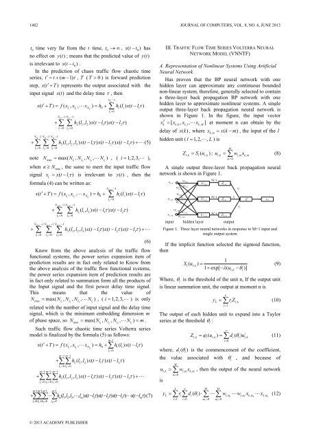
hidden layer to approximate nonl<strong>in</strong>ear systems. A s<strong>in</strong>gle<br />
output three-layer back propagation neural network is<br />
shown <strong>in</strong> Figure 1. In the figure, the <strong>in</strong>put vector<br />
T<br />
x = [ x , x , x ] at moment n can obta<strong>in</strong> by the<br />
k k,0 k,1 k,<br />
M<br />
delay of x( k ), where x<br />
,<br />
= xk ( − m)<br />
, the <strong>in</strong>put of the l<br />
km<br />
hidden unit ( l = 1, 2, , L) is<br />
Z<br />
= S ( u ); ulk ,<br />
= ∑ wlm ,<br />
xkm<br />
,<br />
(8)<br />
lk , l lk ,<br />
M<br />
m=<br />
0<br />
A s<strong>in</strong>gle output three-layer back propagation neural<br />
network is shown <strong>in</strong> Figure 1.<br />
x k,0<br />
x km ,<br />
x kM ,<br />
w L , m<br />
w 1,0<br />
w<br />
,0<br />
w l<br />
L,0<br />
w 1,m<br />
w lm ,<br />
w 1,M<br />
w lM ,<br />
w L , M<br />
U 1,k<br />
U lk ,<br />
U L , k<br />
S()<br />
⋅<br />
S()<br />
⋅<br />
S()<br />
⋅<br />
Z 1,k<br />
Z lk ,<br />
Z L , k<br />
<strong>in</strong>put hidden layer output<br />
Figure 1. Three layer neural networks <strong>in</strong> response to M+1 <strong>in</strong>put and<br />
s<strong>in</strong>gle output system<br />
If the implicit function selected the sigmoid function,<br />
then<br />
1<br />
Sl( u<br />
,<br />
) = l k<br />
1 + exp[ − λ( u − θ )]<br />
(9)<br />
Where, θ<br />
l<br />
is the threshold of the unit n, If the output unit<br />
is l<strong>in</strong>ear summation unit, the output at moment n is<br />
y<br />
L<br />
r l<br />
lk ,<br />
r 1<br />
r L<br />
k l l,<br />
k<br />
l = 1<br />
l<br />
Z<br />
= ∑ rZ<br />
(10)<br />
The output of each hidden unit to expand <strong>in</strong>to a Taylor<br />
series at the threshold θ<br />
l<br />
:<br />
Z = ϕ ( u ) =∑ d ( θ ) u<br />
i<br />
(11)<br />
l, k l l, k i l l,<br />
k<br />
i=<br />
0<br />
where, d ( θ ) is the commencement of the coefficient,<br />
i<br />
l<br />
the value associated with<br />
M<br />
lk , lm , km ,<br />
m=<br />
0<br />
∞<br />
θ<br />
l<br />
y k<br />
, and because of<br />
u = ∑ w x , then the output of the neural network<br />
is<br />
L ∞<br />
M M<br />
∑∑ ∑ ∑<br />
y = r d ( θ ) ⋅ w w x x (12)<br />
k l i l l, m1 l, mi<br />
k, m1<br />
k,<br />
mi<br />
l= 1 i= 0 m1<br />
= 0 mi<br />
= 0<br />
© 2013 ACADEMY PUBLISHER


