

Download Full Issue in PDF - Academy Publisher
Download Full Issue in PDF - Academy Publisher
Download Full Issue in PDF - Academy Publisher

You also want an ePaper? Increase the reach of your titles
YUMPU automatically turns print PDFs into web optimized ePapers that Google loves.
JOURNAL OF COMPUTERS, VOL. 8, NO. 6, JUNE 2013 1465<br />
bridge voltage’, while V ado<br />
between po<strong>in</strong>ts a<br />
d<br />
and o is<br />
‘down bridge voltage’.<br />
1<br />
U<br />
2 d<br />
D a5<br />
S a1<br />
S a2<br />
D a1<br />
a u<br />
D a2<br />
o<br />
1<br />
U<br />
2 d<br />
D a6<br />
S a3<br />
S a4<br />
a<br />
i a<br />
D a3<br />
a d<br />
D a4<br />
Ra<br />
L a<br />
b<br />
n<br />
Rb<br />
L b<br />
c<br />
Rc<br />
L c<br />
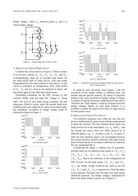
(c) S<br />
a2<br />
open-circuit<br />
Figure 2. S<strong>in</strong>gle bridge leg of NPC <strong>in</strong>verter<br />
A. Open-circuit Fault of S<strong>in</strong>gle Device<br />
Consider the circuit shown <strong>in</strong> Figure 2 which consists<br />
of six devices, namely S<br />
a1<br />
, S<br />
a2<br />
, S<br />
a3<br />
, S<br />
a4<br />
, D<br />
a5<br />
and D<br />
a6<br />
.<br />
Correspond<strong>in</strong>gly, there are six possible fault modes for<br />
the open-circuit fault of s<strong>in</strong>gle device, with each mode<br />
be<strong>in</strong>g denoted by the same symbol of each device. As the<br />
circuit is symmetric <strong>in</strong> configuration, those fault modes<br />
of S<br />
a1<br />
, S<br />
a2<br />
and D<br />
a5<br />
need to be analyzed <strong>in</strong> detail, and<br />
the results apply for the other three fault modes.<br />
Perform<strong>in</strong>g simulation for the NPC <strong>in</strong>verter by the<br />
software PSIM, with the <strong>in</strong>put DC voltage U be<strong>in</strong>g<br />
100V, the load of each phase be<strong>in</strong>g resistance 8Ω and<br />
<strong>in</strong>ductance 20mH <strong>in</strong> series, under the normal (fault free)<br />
condition and each s<strong>in</strong>gle device open-circuit fault mode,<br />
the simulation waveforms of bridge voltage could be<br />
obta<strong>in</strong>ed as shown <strong>in</strong> Figure 3.<br />
(a) Fault free mode<br />
(b) S<br />
a1<br />
open-circuit<br />
d<br />
(d) D<br />
a5<br />
open-circuit<br />
Figure 3. Simulation waveforms of bridge voltage for open-circuit<br />
fault of s<strong>in</strong>gle device<br />
It could be seen obviously from Figure 3 that the<br />
waveform of the bridge voltage is different from one<br />
another and has specific features. By theory of spectrum<br />
analysis [18], each waveform of bridge voltage <strong>in</strong> Figure<br />
3 consists of specific harmonics differ<strong>in</strong>g from the other’s.<br />
Therefore the ‘fault features’ could be extracted from the<br />
bridge voltages. Based on such fault features, it is<br />
possible to isolate the open-circuit fault of s<strong>in</strong>gle device<br />
<strong>in</strong> some proper ways.<br />
B. Open-circuit Fault of Two Devices<br />
Two different situations arise while the case that two<br />
devices malfunction by open-circuit dur<strong>in</strong>g certa<strong>in</strong> period<br />
is taken <strong>in</strong>to account. The first situation arises when two<br />
faulty devices lie <strong>in</strong> the same phase, e.g. S<br />
a1<br />
and S<br />
a3<br />
, and<br />
the second one arises when two faulty devices lie <strong>in</strong><br />
different phases, e.g. S<br />
a1<br />
<strong>in</strong> phase a and S<br />
b1<br />
<strong>in</strong> phase b.<br />
Only the first situation needs to be <strong>in</strong>vestigated because<br />
the second situation could be reduced to the open-circuit<br />
fault of s<strong>in</strong>gle device <strong>in</strong> two phases and then be treated by<br />
the way mentioned above.<br />
Consider<strong>in</strong>g the phase a without loss of generality,<br />
possibly there are six different fault modes as { S<br />
a1<br />
, S<br />
a2<br />
},<br />
{ S<br />
a1<br />
, S<br />
a3<br />
}, { S<br />
a1<br />
, S<br />
a4<br />
}, { S<br />
a2<br />
, S<br />
a3<br />
}, { S<br />
a2<br />
, S<br />
a4<br />
} and<br />
{ S<br />
a3<br />
, S<br />
a4<br />
}. Due to the symmetry <strong>in</strong> the configuration of<br />
NPC <strong>in</strong>verter, for the fault modes { S<br />
a2<br />
, S<br />
a4<br />
} and { S<br />
a3<br />
,<br />
S<br />
a4<br />
}, the bridge voltage would be the same as one for<br />
{ S<br />
a1<br />
, S<br />
a3<br />
} and { S<br />
a1<br />
, S<br />
a2<br />
} respectively, while the phase<br />
is just opposite. Therefore only the other four fault modes<br />
should be analyzed. The bridge voltages’ simulation for<br />
these four faulty modes is given out <strong>in</strong> Figure 4.<br />
© 2013 ACADEMY PUBLISHER


