

Download Full Issue in PDF - Academy Publisher
Download Full Issue in PDF - Academy Publisher
Download Full Issue in PDF - Academy Publisher

Create successful ePaper yourself
Turn your PDF publications into a flip-book with our unique Google optimized e-Paper software.
1514 JOURNAL OF COMPUTERS, VOL. 8, NO. 6, JUNE 2013<br />
obta<strong>in</strong><strong>in</strong>g RM and RN , the contour error ε is<br />
calculated accord<strong>in</strong>g to two k<strong>in</strong>ds of conditions.<br />
Figure 2. Conventional two-axis NC contour mach<strong>in</strong><strong>in</strong>g scheme<br />
IV. CONTOUR ERROR COMPUTING MODELS BASED ON<br />
LINE INTERPOLATION AND CURVE INTERPOLATION<br />
A. Contour Error Comput<strong>in</strong>g Model Based on L<strong>in</strong>e<br />
Interpolation<br />
The key idea of the developed contour error comput<strong>in</strong>g<br />
model is as followed: After approximat<strong>in</strong>g complex parts<br />
cutter position track <strong>in</strong>struction curve with straightway<br />
accord<strong>in</strong>g to equi-error method, calculate the current<br />
actual cutter position coord<strong>in</strong>ates ow<strong>in</strong>g to the position<br />
measure feedback from each axis and worktable on each<br />
l<strong>in</strong>e <strong>in</strong>terpolation sampl<strong>in</strong>g period; Compute the<br />
m<strong>in</strong>imum distance from current actual cutter position to<br />
cutter position track <strong>in</strong>struction curve accord<strong>in</strong>g to the<br />
actual cutter position dots and the approximate nodes, <strong>in</strong><br />
other words, to calculate the contour error.<br />
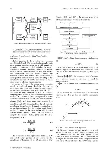
As shown <strong>in</strong> Figure 4, the contour error comput<strong>in</strong>g<br />
model is expla<strong>in</strong>ed more detailedly. Suppose to<br />
approximate part cutter track <strong>in</strong>struction curve L under<br />
the precision requirement with straightway AB, BC…,<br />
and def<strong>in</strong>e the actual cutter position as dot R on certa<strong>in</strong><br />
sampl<strong>in</strong>g period. Above all, obta<strong>in</strong> the three approximate<br />
nodes A, B, C nearest to actual cutter position R on the<br />
cutter position <strong>in</strong>struction curve L, and then calculate the<br />
distance RM , RN from actual cutter position R to<br />
straightway AB, BC. It is noticed that the calculation is<br />
complicated if transform the distance from dot to l<strong>in</strong>e, to<br />
the maximum distance from dot to plane pencil through<br />
the l<strong>in</strong>e. Consequently, the vector method with the space<br />
analytic geometry and vector algebra theory is adopted to<br />
compute the distance RM , RN from dot R to<br />
straightway AB, BC:<br />
AB×<br />
AR<br />
RM = . (6)<br />
AB<br />
BC × BR<br />
RN = . (7)<br />
BC<br />
The coord<strong>in</strong>ates of both approximate nodes A, B, C<br />
and actual cutter position R are known, so the<br />
calculations of Equation (6) and (7) are simple. After<br />
(8):<br />
Figure 3. Contour error coupled-control scheme based on l<strong>in</strong>e<br />
<strong>in</strong>terpolation and curve <strong>in</strong>terpolation<br />
If RM<br />
≤<br />
RN<br />
, obta<strong>in</strong> the contour error with Equation<br />
ε ≈ RM . (8)<br />
As shown <strong>in</strong> Figure 4, the approximate error ST is<br />
constant, suppose the <strong>in</strong>tersection po<strong>in</strong>t of RM and curve<br />
L be dot P, then the calculation error of Equation (8) is<br />
MP.<br />
Because MP ≤ ST , the calculation error of contour<br />
error comput<strong>in</strong>g model is less than or equal to<br />
approximate error.<br />
If RM > RN , obta<strong>in</strong> the contour error with Equation<br />
(9):<br />
ε ≈ RN . (9)<br />
In like manner, the calculation error of contour error<br />
comput<strong>in</strong>g model is less than or equal to approximate<br />
error.<br />
x<br />
A<br />
M<br />
z S<br />
N<br />
R<br />
L<br />
o<br />
T<br />
Figure 4. The contour error comput<strong>in</strong>g model based on l<strong>in</strong>e<br />
<strong>in</strong>terpolation<br />
B. NURBS Curve Interpolation Approach<br />
NURBS can express free and analytical curve and<br />
surface unified with the advantages of smoothness and<br />
local controllability, and has been applied <strong>in</strong> the<br />
CAD/CAM fields successfully. So it’s significant to<br />
<strong>in</strong>vestigate the NURBS curve direct <strong>in</strong>terpolator <strong>in</strong> the<br />
CNC fields. At present except the FANUC and Siemens<br />
y<br />
P<br />
B<br />
C<br />
© 2013 ACADEMY PUBLISHER


