

Download Full Issue in PDF - Academy Publisher
Download Full Issue in PDF - Academy Publisher
Download Full Issue in PDF - Academy Publisher

You also want an ePaper? Increase the reach of your titles
YUMPU automatically turns print PDFs into web optimized ePapers that Google loves.
1516 JOURNAL OF COMPUTERS, VOL. 8, NO. 6, JUNE 2013<br />
ε<br />
y<br />
= ε ∗<br />
M<br />
y<br />
− O<br />
( M − O ) + ( M − O ) + ( M −O<br />
)<br />
2 2 2<br />
x x y y z z<br />
y<br />
. (17)<br />
ε<br />
z<br />
= ε ∗<br />
M<br />
z<br />
− O<br />
( M − O ) + ( M − O ) + ( M −O<br />
)<br />
2 2 2<br />
x x y y z z<br />
z<br />
. (18)<br />
In conclusion, the contour error comput<strong>in</strong>g model<br />
approximates curve L <strong>in</strong> locality with arc properly, so<br />
higher precision will be achieved.<br />
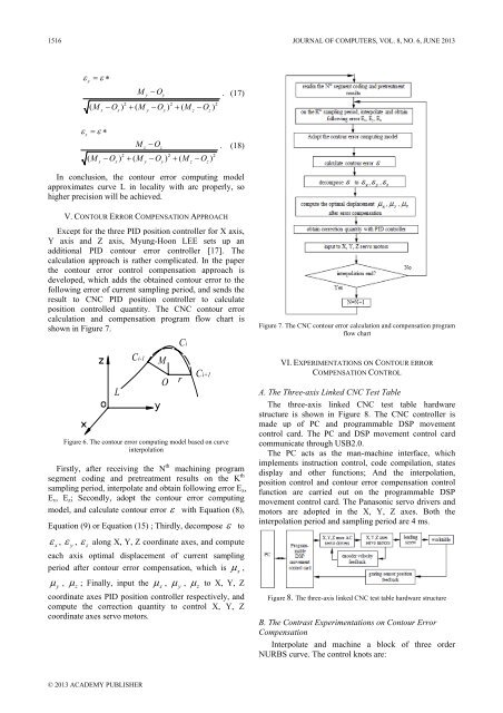
V. CONTOUR ERROR COMPENSATION APPROACH<br />
Except for the three PID position controller for X axis,<br />
Y axis and Z axis, Myung-Hoon LEE sets up an<br />
additional PID contour error controller [17]. The<br />
calculation approach is rather complicated. In the paper<br />
the contour error control compensation approach is<br />
developed, which adds the obta<strong>in</strong>ed contour error to the<br />
follow<strong>in</strong>g error of current sampl<strong>in</strong>g period, and sends the<br />
result to CNC PID position controller to calculate<br />
position controlled quantity. The CNC contour error<br />
calculation and compensation program flow chart is<br />
shown <strong>in</strong> Figure 7.<br />
L<br />
Ci-1<br />
M<br />
O<br />
Ci<br />
r<br />
Ci+1<br />
Figure 6. The contour error comput<strong>in</strong>g model based on curve<br />
<strong>in</strong>terpolation<br />
Firstly, after receiv<strong>in</strong>g the N th mach<strong>in</strong><strong>in</strong>g program<br />
segment cod<strong>in</strong>g and pretreatment results on the K th<br />
sampl<strong>in</strong>g period, <strong>in</strong>terpolate and obta<strong>in</strong> follow<strong>in</strong>g error E x ,<br />
E y , E z ; Secondly, adopt the contour error comput<strong>in</strong>g<br />
model, and calculate contour error ε with Equation (8),<br />
Equation (9) or Equation (15) ; Thirdly, decompose ε to<br />
ε<br />
x<br />
, ε<br />
y<br />
, ε<br />
z<br />
along X, Y, Z coord<strong>in</strong>ate axes, and compute<br />
each axis optimal displacement of current sampl<strong>in</strong>g<br />
period after contour error compensation, which is μ ,<br />
μ , μ ; F<strong>in</strong>ally, <strong>in</strong>put the μ , μ ,<br />
y<br />
z<br />
x<br />
y<br />
μ<br />
z<br />
to X, Y, Z<br />
coord<strong>in</strong>ate axes PID position controller respectively, and<br />
compute the correction quantity to control X, Y, Z<br />
coord<strong>in</strong>ate axes servo motors.<br />
x<br />
Figure 7. The CNC contour error calculation and compensation program<br />
flow chart<br />
VI. EXPERIMENTATIONS ON CONTOUR ERROR<br />
COMPENSATION CONTROL<br />
A. The Three-axis L<strong>in</strong>ked CNC Test Table<br />
The three-axis l<strong>in</strong>ked CNC test table hardware<br />
structure is shown <strong>in</strong> Figure 8. The CNC controller is<br />
made up of PC and programmable DSP movement<br />
control card. The PC and DSP movement control card<br />
communicate through USB2.0.<br />
The PC acts as the man-mach<strong>in</strong>e <strong>in</strong>terface, which<br />
implements <strong>in</strong>struction control, code compilation, states<br />
display and other functions; And the <strong>in</strong>terpolation,<br />
position control and contour error compensation control<br />
function are carried out on the programmable DSP<br />
movement control card. The Panasonic servo drivers and<br />
motors are adopted <strong>in</strong> the X, Y, Z axes. Both the<br />
<strong>in</strong>terpolation period and sampl<strong>in</strong>g period are 4 ms.<br />
Figure 8. The three-axis l<strong>in</strong>ked CNC test table hardware structure<br />
B. The Contrast Experimentations on Contour Error<br />
Compensation<br />
Interpolate and mach<strong>in</strong>e a block of three order<br />
NURBS curve. The control knots are:<br />
© 2013 ACADEMY PUBLISHER


