

Download Full Issue in PDF - Academy Publisher
Download Full Issue in PDF - Academy Publisher
Download Full Issue in PDF - Academy Publisher

You also want an ePaper? Increase the reach of your titles
YUMPU automatically turns print PDFs into web optimized ePapers that Google loves.
1466 JOURNAL OF COMPUTERS, VOL. 8, NO. 6, JUNE 2013<br />
(a) { S<br />
a1<br />
, S<br />
a2<br />
}<br />
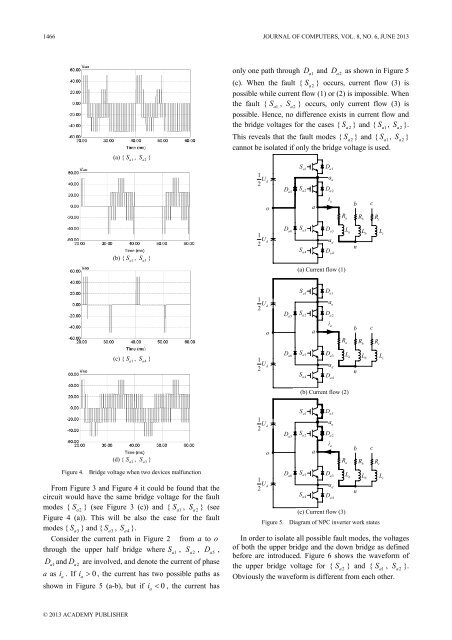
only one path through D<br />
a1<br />
and D<br />
a2<br />
as shown <strong>in</strong> Figure 5<br />
(c). When the fault { S<br />
a2<br />
} occurs, current flow (3) is<br />
possible while current flow (1) or (2) is impossible. When<br />
the fault { S<br />
a1<br />
, S<br />
a2<br />
} occurs, only current flow (3) is<br />
possible. Hence, no difference exists <strong>in</strong> current flow and<br />
the bridge voltages for the cases { S<br />
a2<br />
} and { S<br />
a1<br />
, S<br />
a2<br />
}.<br />
This reveals that the fault modes { S<br />
a2<br />
} and { S<br />
a1<br />
, S<br />
a2<br />
}<br />
cannot be isolated if only the bridge voltage is used.<br />
1<br />
U<br />
2 d<br />
D a5<br />
S a1<br />
S a2<br />
D a1<br />
a u<br />
D a2<br />
o<br />
a<br />
i a<br />
Ra<br />
b<br />
Rb<br />
c<br />
Rc<br />
(b) { S<br />
a1<br />
, S<br />
a3<br />
}<br />
1<br />
U<br />
2 d<br />
D a6<br />
S a3<br />
S a4<br />
D a3<br />
a d<br />
D a4<br />
L a<br />
n<br />
L b<br />
L c<br />
(a) Current flow (1)<br />
1<br />
U<br />
2 d<br />
D a5<br />
S a1<br />
S a2<br />
D a1<br />
a u<br />
D a2<br />
o<br />
a<br />
i a<br />
R a<br />
b<br />
Rb<br />
c<br />
Rc<br />
(c) { S<br />
a1<br />
, S<br />
a4<br />
}<br />
1<br />
U<br />
2 d<br />
D a6<br />
S a3<br />
S a4<br />
D a3<br />
a d<br />
D a4<br />
L a<br />
n<br />
L b<br />
L c<br />
(b) Current flow (2)<br />
1<br />
U<br />
2 d<br />
D a5<br />
S a1<br />
S a2<br />
D a1<br />
a u<br />
D a2<br />
(d) { S<br />
a2<br />
, S<br />
a3<br />
}<br />
Figure 4. Bridge voltage when two devices malfunction<br />
From Figure 3 and Figure 4 it could be found that the<br />
circuit would have the same bridge voltage for the fault<br />
modes { S<br />
a2<br />
} (see Figure 3 (c)) and { S<br />
a1<br />
, S<br />
a2<br />
} (see<br />
Figure 4 (a)). This will be also the case for the fault<br />
modes { S<br />
a3<br />
} and { S<br />
a3<br />
, S<br />
a4<br />
}.<br />
Consider the current path <strong>in</strong> Figure 2 from a to o<br />
through the upper half bridge where S<br />
a1<br />
, S<br />
a2<br />
, D<br />
a5<br />
,<br />
Da1<br />
and D<br />
a2<br />
are <strong>in</strong>volved, and denote the current of phase<br />
a as i a<br />
. If i<br />
a<br />
> 0 , the current has two possible paths as<br />
shown <strong>in</strong> Figure 5 (a-b), but if i<br />
a<br />
< 0 , the current has<br />
o<br />
1<br />
U<br />
2 d<br />
D a6<br />
S a3<br />
S a4<br />
a<br />
i a<br />
D a3<br />
a d<br />
D a4<br />
Ra<br />
(c) Current flow (3)<br />
L a<br />
b<br />
n<br />
Rb<br />
L b<br />
c<br />
Rc<br />
Figure 5. Diagram of NPC <strong>in</strong>verter work states<br />
In order to isolate all possible fault modes, the voltages<br />
of both the upper bridge and the down bridge as def<strong>in</strong>ed<br />
before are <strong>in</strong>troduced. Figure 6 shows the waveform of<br />
the upper bridge voltage for { S<br />
a2<br />
} and { S<br />
a1<br />
, S<br />
a2<br />
}.<br />
Obviously the waveform is different from each other.<br />
L c<br />
© 2013 ACADEMY PUBLISHER


