

Chapter A General rules of electrical installation design
Chapter A General rules of electrical installation design
Chapter A General rules of electrical installation design

You also want an ePaper? Increase the reach of your titles
YUMPU automatically turns print PDFs into web optimized ePapers that Google loves.
© Schneider Electric - all rights reserved<br />
E2<br />
E - Distribution in low-voltage <strong>installation</strong>s<br />
In a building, the connection <strong>of</strong> all metal parts<br />
<strong>of</strong> the building and all exposed conductive parts<br />
<strong>of</strong> <strong>electrical</strong> equipment to an earth electrode<br />
prevents the appearance <strong>of</strong> dangerously high<br />
voltages between any two simultaneously<br />
accessible metal parts<br />
4<br />
Extraneous<br />
conductive<br />
parts<br />
4<br />
Heating<br />
Water<br />
Branched<br />
protective<br />
conductors<br />
to individual<br />
consumers<br />
Gas<br />
5<br />
1<br />
5<br />
5<br />
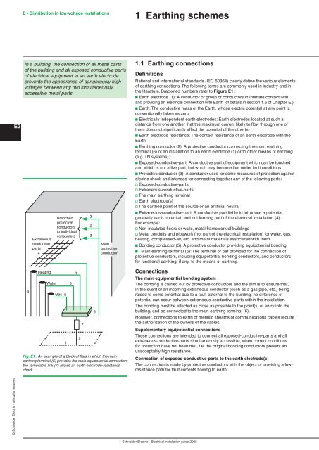
Fig. E1 : An example <strong>of</strong> a block <strong>of</strong> flats in which the main<br />
earthing terminal (6) provides the main equipotential connection;<br />
the removable link (7) allows an earth-electrode-resistance<br />
check<br />
2<br />
7<br />
3<br />
3<br />
3<br />
6<br />
Main<br />
protective<br />
conductor<br />
Earthing schemes<br />
. Earthing connections<br />
Definitions<br />
National and international standards (IEC 60364) clearly define the various elements<br />
<strong>of</strong> earthing connections. The following terms are commonly used in industry and in<br />
the literature. Bracketed numbers refer to Figure E :<br />
b Earth electrode (1): A conductor or group <strong>of</strong> conductors in intimate contact with,<br />
and providing an <strong>electrical</strong> connection with Earth (cf details in section 1.6 <strong>of</strong> <strong>Chapter</strong> E.)<br />
b Earth: The conductive mass <strong>of</strong> the Earth, whose electric potential at any point is<br />
conventionally taken as zero<br />
b Electrically independent earth electrodes: Earth electrodes located at such a<br />
distance from one another that the maximum current likely to flow through one <strong>of</strong><br />
them does not significantly affect the potential <strong>of</strong> the other(s)<br />
b Earth electrode resistance: The contact resistance <strong>of</strong> an earth electrode with the<br />
Earth<br />
b Earthing conductor (2): A protective conductor connecting the main earthing<br />
terminal (6) <strong>of</strong> an <strong>installation</strong> to an earth electrode (1) or to other means <strong>of</strong> earthing<br />
(e.g. TN systems);<br />
b Exposed-conductive-part: A conductive part <strong>of</strong> equipment which can be touched<br />
and which is not a live part, but which may become live under fault conditions<br />
b Protective conductor (3): A conductor used for some measures <strong>of</strong> protection against<br />
electric shock and intended for connecting together any <strong>of</strong> the following parts:<br />
v Exposed-conductive-parts<br />
v Extraneous-conductive-parts<br />
v The main earthing terminal<br />
v Earth electrode(s)<br />
v The earthed point <strong>of</strong> the source or an artificial neutral<br />
b Extraneous-conductive-part: A conductive part liable to introduce a potential,<br />
generally earth potential, and not forming part <strong>of</strong> the <strong>electrical</strong> <strong>installation</strong> (4).<br />
For example:<br />
v Non-insulated floors or walls, metal framework <strong>of</strong> buildings<br />
v Metal conduits and pipework (not part <strong>of</strong> the <strong>electrical</strong> <strong>installation</strong>) for water, gas,<br />
heating, compressed-air, etc. and metal materials associated with them<br />
b Bonding conductor (5): A protective conductor providing equipotential bonding<br />
b Main earthing terminal (6): The terminal or bar provided for the connection <strong>of</strong><br />
protective conductors, including equipotential bonding conductors, and conductors<br />
for functional earthing, if any, to the means <strong>of</strong> earthing.<br />
Connections<br />
The main equipotential bonding system<br />
The bonding is carried out by protective conductors and the aim is to ensure that,<br />
in the event <strong>of</strong> an incoming extraneous conductor (such as a gas pipe, etc.) being<br />
raised to some potential due to a fault external to the building, no difference <strong>of</strong><br />
potential can occur between extraneous-conductive-parts within the <strong>installation</strong>.<br />
The bonding must be effected as close as possible to the point(s) <strong>of</strong> entry into the<br />
building, and be connected to the main earthing terminal (6).<br />
However, connections to earth <strong>of</strong> metallic sheaths <strong>of</strong> communications cables require<br />
the authorisation <strong>of</strong> the owners <strong>of</strong> the cables.<br />
Supplementary equipotential connections<br />
These connections are intended to connect all exposed-conductive-parts and all<br />
extraneous-conductive-parts simultaneously accessible, when correct conditions<br />
for protection have not been met, i.e. the original bonding conductors present an<br />
unacceptably high resistance.<br />
Connection <strong>of</strong> exposed-conductive-parts to the earth electrode(s)<br />
The connection is made by protective conductors with the object <strong>of</strong> providing a lowresistance<br />
path for fault currents flowing to earth.<br />
Schneider Electric - Electrical <strong>installation</strong> guide 2008


