

Chapter A General rules of electrical installation design
Chapter A General rules of electrical installation design
Chapter A General rules of electrical installation design

Create successful ePaper yourself
Turn your PDF publications into a flip-book with our unique Google optimized e-Paper software.
© Schneider Electric - all rights reserved<br />
H8<br />
H - LV switchgear: functions & selection<br />
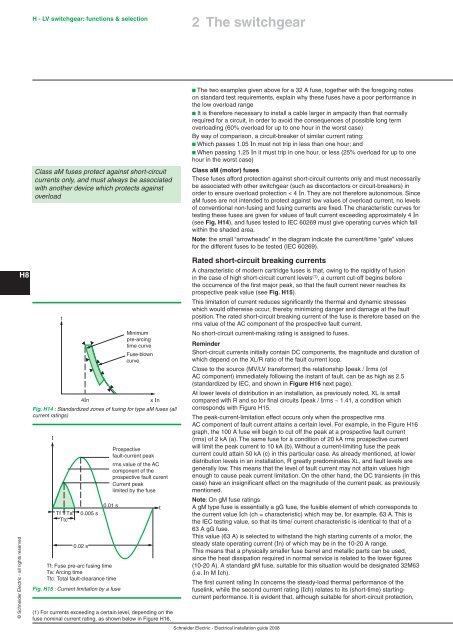
Class aM fuses protect against short-circuit<br />
currents only, and must always be associated<br />
with another device which protects against<br />
overload<br />
4 I n<br />
x I n<br />
Fig. H14 : Standardized zones <strong>of</strong> fusing for type aM fuses (all<br />
current ratings)<br />
I<br />
t<br />
Tf Ta<br />
Ttc<br />
0.005 s<br />
0.02 s<br />
0.01 s<br />
Tf: Fuse pre-arc fusing time<br />
Ta: Arcing time<br />
Ttc: Total fault-clearance time<br />
Fig. H15 : Current limitation by a fuse<br />
Mini m um<br />
pre-arcing<br />
time cu r v e<br />
Fuse- b l o wn<br />
cu r v e<br />
Prospective<br />
fault-current peak<br />
rms value <strong>of</strong> the AC<br />
component <strong>of</strong> the<br />
prospective fault curent<br />
Current peak<br />
limited by the fuse<br />
(1) For currents exceeding a certain level, depending on the<br />
fuse nominal current rating, as shown below in Figure H16.<br />
t<br />
2 The switchgear<br />
b The two examples given above for a 32 A fuse, together with the foregoing notes<br />
on standard test requirements, explain why these fuses have a poor performance in<br />
the low overload range<br />
b It is therefore necessary to install a cable larger in ampacity than that normally<br />
required for a circuit, in order to avoid the consequences <strong>of</strong> possible long term<br />
overloading (60% overload for up to one hour in the worst case)<br />
By way <strong>of</strong> comparison, a circuit-breaker <strong>of</strong> similar current rating:<br />
b Which passes 1.05 In must not trip in less than one hour; and<br />
b When passing 1.25 In it must trip in one hour, or less (25% overload for up to one<br />
hour in the worst case)<br />
Class aM (motor) fuses<br />
These fuses afford protection against short-circuit currents only and must necessarily<br />
be associated with other switchgear (such as discontactors or circuit-breakers) in<br />
order to ensure overload protection < 4 In. They are not therefore autonomous. Since<br />
aM fuses are not intended to protect against low values <strong>of</strong> overload current, no levels<br />
<strong>of</strong> conventional non-fusing and fusing currents are fixed. The characteristic curves for<br />
testing these fuses are given for values <strong>of</strong> fault current exceeding approximately 4 In<br />
(see Fig. H14), and fuses tested to IEC 60269 must give operating curves which fall<br />
within the shaded area.<br />
Note: the small “arrowheads” in the diagram indicate the current/time “gate” values<br />
for the different fuses to be tested (IEC 60269).<br />
Rated short-circuit breaking currents<br />
A characteristic <strong>of</strong> modern cartridge fuses is that, owing to the rapidity <strong>of</strong> fusion<br />
in the case <strong>of</strong> high short-circuit current levels (1) , a current cut-<strong>of</strong>f begins before<br />
the occurrence <strong>of</strong> the first major peak, so that the fault current never reaches its<br />
prospective peak value (see Fig. H1 ).<br />
This limitation <strong>of</strong> current reduces significantly the thermal and dynamic stresses<br />
which would otherwise occur, thereby minimizing danger and damage at the fault<br />
position. The rated short-circuit breaking current <strong>of</strong> the fuse is therefore based on the<br />
rms value <strong>of</strong> the AC component <strong>of</strong> the prospective fault current.<br />
No short-circuit current-making rating is assigned to fuses.<br />
Reminder<br />
Short-circuit currents initially contain DC components, the magnitude and duration <strong>of</strong><br />
which depend on the XL/R ratio <strong>of</strong> the fault current loop.<br />
Close to the source (MV/LV transformer) the relationship Ipeak / Irms (<strong>of</strong><br />
AC component) immediately following the instant <strong>of</strong> fault, can be as high as 2.5<br />
(standardized by IEC, and shown in Figure H16 next page).<br />
At lower levels <strong>of</strong> distribution in an <strong>installation</strong>, as previously noted, XL is small<br />
compared with R and so for final circuits Ipeak / Irms ~ 1.41, a condition which<br />
corresponds with Figure H15.<br />
The peak-current-limitation effect occurs only when the prospective rms<br />
AC component <strong>of</strong> fault current attains a certain level. For example, in the Figure H16<br />
graph, the 100 A fuse will begin to cut <strong>of</strong>f the peak at a prospective fault current<br />
(rms) <strong>of</strong> 2 kA (a). The same fuse for a condition <strong>of</strong> 20 kA rms prospective current<br />
will limit the peak current to 10 kA (b). Without a current-limiting fuse the peak<br />
current could attain 50 kA (c) in this particular case. As already mentioned, at lower<br />
distribution levels in an <strong>installation</strong>, R greatly predominates XL, and fault levels are<br />
generally low. This means that the level <strong>of</strong> fault current may not attain values high<br />
enough to cause peak current limitation. On the other hand, the DC transients (in this<br />
case) have an insignificant effect on the magnitude <strong>of</strong> the current peak, as previously<br />
mentioned.<br />
Note: On gM fuse ratings<br />
A gM type fuse is essentially a gG fuse, the fusible element <strong>of</strong> which corresponds to<br />
the current value Ich (ch = characteristic) which may be, for example, 63 A. This is<br />
the IEC testing value, so that its time/ current characteristic is identical to that <strong>of</strong> a<br />
63 A gG fuse.<br />
This value (63 A) is selected to withstand the high starting currents <strong>of</strong> a motor, the<br />
steady state operating current (In) <strong>of</strong> which may be in the 10-20 A range.<br />
This means that a physically smaller fuse barrel and metallic parts can be used,<br />
since the heat dissipation required in normal service is related to the lower figures<br />
(10-20 A). A standard gM fuse, suitable for this situation would be <strong>design</strong>ated 32M63<br />
(i.e. In M Ich).<br />
The first current rating In concerns the steady-load thermal performance <strong>of</strong> the<br />
fuselink, while the second current rating (Ich) relates to its (short-time) startingcurrent<br />
performance. It is evident that, although suitable for short-circuit protection,<br />
Schneider Electric - Electrical <strong>installation</strong> guide 2008


