

Chapter A General rules of electrical installation design
Chapter A General rules of electrical installation design
Chapter A General rules of electrical installation design

You also want an ePaper? Increase the reach of your titles
YUMPU automatically turns print PDFs into web optimized ePapers that Google loves.
© Schneider Electric - all rights reserved<br />
H2<br />
H - LV switchgear: functions & selection<br />
The role <strong>of</strong> switchgear is:<br />
b Electrical protection<br />
b Safe isolation from live parts<br />
b Local or remote switching<br />
Electrical protection assures:<br />
b Protection <strong>of</strong> circuit elements against the<br />
thermal and mechanical stresses <strong>of</strong> short-circuit<br />
currents<br />
b Protection <strong>of</strong> persons in the event <strong>of</strong><br />
insulation failure<br />
b Protection <strong>of</strong> appliances and apparatus being<br />
supplied (e.g. motors, etc.)<br />
The basic functions <strong>of</strong><br />
LV switchgear<br />
National and international standards define the manner in which electric circuits <strong>of</strong><br />
LV <strong>installation</strong>s must be realized, and the capabilities and limitations <strong>of</strong> the various<br />
switching devices which are collectively referred to as switchgear.<br />
The main functions <strong>of</strong> switchgear are:<br />
b Electrical protection<br />
b Electrical isolation <strong>of</strong> sections <strong>of</strong> an <strong>installation</strong><br />
b Local or remote switching<br />
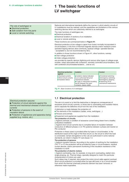
These functions are summarized below in Figure H .<br />
Electrical protection at low voltage is (apart from fuses) normally incorporated in<br />
circuit-breakers, in the form <strong>of</strong> thermal-magnetic devices and/or residual-currentoperated<br />
tripping devices (less-commonly, residual voltage- operated devices<br />
- acceptable to, but not recommended by IEC).<br />
In addition to those functions shown in Figure H1, other functions, namely:<br />
b Over-voltage protection<br />
b Under-voltage protection<br />
are provided by specific devices (lightning and various other types <strong>of</strong> voltage-surge<br />
arrester, relays associated with contactors, remotely controlled circuit-breakers, and<br />
with combined circuit-breaker/isolators… and so on)<br />
Electrical protection Isolation Control<br />
against<br />
b Overload currents b Isolation clearly indicated b Functional switching<br />
b Short-circuit currents by an authorized fail-pro<strong>of</strong> b Emergency switching<br />
b Insulation failure mechanical indicator b Emergency stopping<br />
b A gap or interposed insulating b Switching <strong>of</strong>f for<br />
barrier between the open mechanical maintenance<br />
contacts, clearly visible<br />
Fig. H1 : Basic functions <strong>of</strong> LV switchgear<br />
. Electrical protection<br />
The aim is to avoid or to limit the destructive or dangerous consequences <strong>of</strong><br />
excessive (short-circuit) currents, or those due to overloading and insulation failure,<br />
and to separate the defective circuit from the rest <strong>of</strong> the <strong>installation</strong>.<br />
A distinction is made between the protection <strong>of</strong>:<br />
b The elements <strong>of</strong> the <strong>installation</strong> (cables, wires, switchgear…)<br />
b Persons and animals<br />
b Equipment and appliances supplied from the <strong>installation</strong><br />
The protection <strong>of</strong> circuits<br />
v Against overload; a condition <strong>of</strong> excessive current being drawn from a healthy<br />
(unfaulted) <strong>installation</strong><br />
v Against short-circuit currents due to complete failure <strong>of</strong> insulation between<br />
conductors <strong>of</strong> different phases or (in TN systems) between a phase and neutral (or<br />
PE) conductor<br />
Protection in these cases is provided either by fuses or circuit-breaker, in the<br />
distribution board at the origin <strong>of</strong> the final circuit (i.e. the circuit to which the load<br />
is connected). Certain derogations to this rule are authorized in some national<br />
standards, as noted in chapter H1 sub-clause 1.4.<br />
The protection <strong>of</strong> persons<br />
v Against insulation failures. According to the system <strong>of</strong> earthing for the <strong>installation</strong><br />
(TN, TT or IT) the protection will be provided by fuses or circuit-breakers, residual<br />
current devices, and/or permanent monitoring <strong>of</strong> the insulation resistance <strong>of</strong> the<br />
<strong>installation</strong> to earth<br />
The protection <strong>of</strong> electric motors<br />
v Against overheating, due, for example, to long term overloading, stalled rotor,<br />
single-phasing, etc. Thermal relays, specially <strong>design</strong>ed to match the particular<br />
characteristics <strong>of</strong> motors are used.<br />
Such relays may, if required, also protect the motor-circuit cable against overload.<br />
Short-circuit protection is provided either by type aM fuses or by a circuit-breaker<br />
from which the thermal (overload) protective element has been removed, or<br />
otherwise made inoperative.<br />
Schneider Electric - Electrical <strong>installation</strong> guide 2008


