

Chapter A General rules of electrical installation design
Chapter A General rules of electrical installation design
Chapter A General rules of electrical installation design

Create successful ePaper yourself
Turn your PDF publications into a flip-book with our unique Google optimized e-Paper software.
F38<br />
© Schneider Electric - all rights reserved<br />
F - Protection against electric shock<br />
100%<br />
90%<br />
10%<br />
60%<br />
Umax<br />
0.5U<br />
U<br />
1.2 s 50 s<br />
Fig. F68 : Standardized 1.2/50 µs voltage transient wave<br />
1<br />
0.9<br />
0.5<br />
0.1<br />
I<br />
I<br />
ca.0.5 s<br />
10 s (f = 100 kHz)<br />
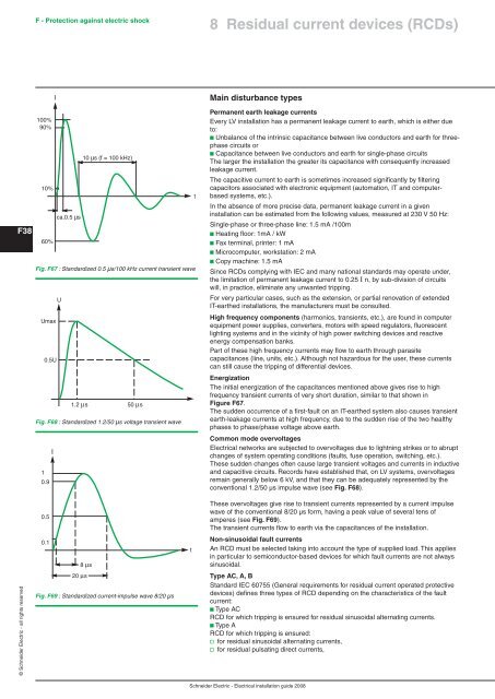
Fig. F67 : Standardized 0.5 µs/100 kHz current transient wave<br />
Fig. F69 : Standardized current-impulse wave 8/20 µs<br />
t<br />
t<br />
t<br />
8 Residual current devices (RCDs)<br />
Main disturbance types<br />
Permanent earth leakage currents<br />
Every LV <strong>installation</strong> has a permanent leakage current to earth, which is either due<br />
to:<br />
b Unbalance <strong>of</strong> the intrinsic capacitance between live conductors and earth for threephase<br />
circuits or<br />
b Capacitance between live conductors and earth for single-phase circuits<br />
The larger the <strong>installation</strong> the greater its capacitance with consequently increased<br />
leakage current.<br />
The capacitive current to earth is sometimes increased significantly by filtering<br />
capacitors associated with electronic equipment (automation, IT and computerbased<br />
systems, etc.).<br />
In the absence <strong>of</strong> more precise data, permanent leakage current in a given<br />
<strong>installation</strong> can be estimated from the following values, measured at 230 V 50 Hz:<br />
Single-phase or three-phase line: 1.5 mA /100m<br />
b Heating floor: 1mA / kW<br />
b Fax terminal, printer: 1 mA<br />
b Microcomputer, workstation: 2 mA<br />
b Copy machine: 1.5 mA<br />
Since RCDs complying with IEC and many national standards may operate under,<br />
the limitation <strong>of</strong> permanent leakage current to 0.25 IΔn, by sub-division <strong>of</strong> circuits<br />
will, in practice, eliminate any unwanted tripping.<br />
For very particular cases, such as the extension, or partial renovation <strong>of</strong> extended<br />
IT-earthed <strong>installation</strong>s, the manufacturers must be consulted.<br />
High frequency components (harmonics, transients, etc.), are found in computer<br />
equipment power supplies, converters, motors with speed regulators, fluorescent<br />
lighting systems and in the vicinity <strong>of</strong> high power switching devices and reactive<br />
energy compensation banks.<br />
Part <strong>of</strong> these high frequency currents may flow to earth through parasite<br />
capacitances (line, units, etc.). Although not hazardous for the user, these currents<br />
can still cause the tripping <strong>of</strong> differential devices.<br />
Energization<br />
The initial energization <strong>of</strong> the capacitances mentioned above gives rise to high<br />
frequency transient currents <strong>of</strong> very short duration, similar to that shown in<br />
Figure F67.<br />
The sudden occurrence <strong>of</strong> a first-fault on an IT-earthed system also causes transient<br />
earth-leakage currents at high frequency, due to the sudden rise <strong>of</strong> the two healthy<br />
phases to phase/phase voltage above earth.<br />
Common mode overvoltages<br />
Electrical networks are subjected to overvoltages due to lightning strikes or to abrupt<br />
changes <strong>of</strong> system operating conditions (faults, fuse operation, switching, etc.).<br />
These sudden changes <strong>of</strong>ten cause large transient voltages and currents in inductive<br />
and capacitive circuits. Records have established that, on LV systems, overvoltages<br />
remain generally below 6 kV, and that they can be adequately represented by the<br />
conventional 1.2/50 μs impulse wave (see Fig. F68).<br />
These overvoltages give rise to transient currents represented by a current impulse<br />
wave <strong>of</strong> the conventional 8/20 μs form, having a peak value <strong>of</strong> several tens <strong>of</strong><br />
amperes (see Fig. F69).<br />
The transient currents flow to earth via the capacitances <strong>of</strong> the <strong>installation</strong>.<br />
Non-sinusoidal fault currents<br />
An RCD must be selected taking into account the type <strong>of</strong> supplied load. This applies<br />
in particular to semiconductor-based devices for which fault currents are not always<br />
sinusoidal.<br />
Type AC, A, B<br />
Standard IEC 60755 (<strong>General</strong> requirements for residual current operated protective<br />
devices) defines three types <strong>of</strong> RCD depending on the characteristics <strong>of</strong> the fault<br />
current:<br />
b Type AC<br />
RCD for which tripping is ensured for residual sinusoidal alternating currents.<br />
b Type A<br />
RCD for which tripping is ensured:<br />
v for residual sinusoidal alternating currents,<br />
v for residual pulsating direct currents,<br />
Schneider Electric - Electrical <strong>installation</strong> guide 2008


