

Chapter A General rules of electrical installation design
Chapter A General rules of electrical installation design
Chapter A General rules of electrical installation design

You also want an ePaper? Increase the reach of your titles
YUMPU automatically turns print PDFs into web optimized ePapers that Google loves.
L - Power factor correction and<br />
harmonic filtering<br />
Improving the power factor <strong>of</strong> an <strong>installation</strong><br />
requires a bank <strong>of</strong> capacitors which acts as a<br />
source <strong>of</strong> reactive energy. This arrangement is<br />
said to provide reactive energy compensation<br />
a) Reactive current components only flow pattern<br />
IL - IC IC IL IL<br />
C L<br />
Load<br />
b) When IC = IL, all reactive power is supplied from the<br />
capacitor bank<br />
IL - IC = 0 IC IL IL<br />
C L<br />
c) With load current added to case (b)<br />
Load<br />
IR IC IR + IL IL IR<br />
C L<br />
Load<br />
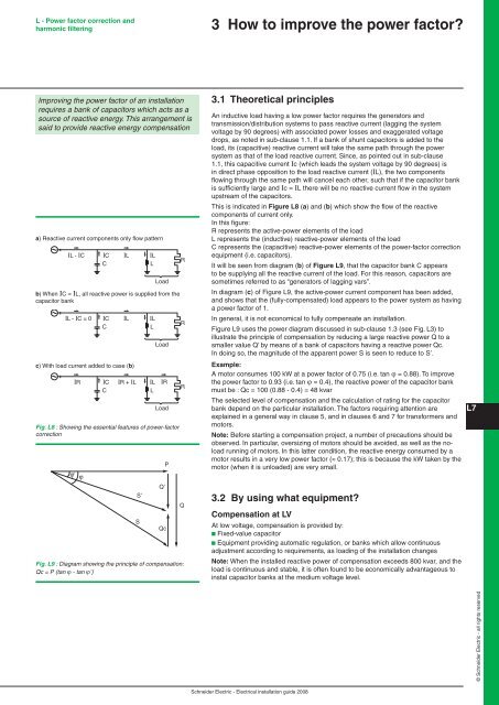
Fig. L8 : Showing the essential features <strong>of</strong> power-factor<br />
correction<br />
ϕ'<br />
ϕ<br />
Qc<br />
Fig. L9 : Diagram showing the principle <strong>of</strong> compensation:<br />
Qc = P (tan ϕ - tan ϕ’)<br />
S'<br />
S<br />
Q'<br />
P<br />
R<br />
R<br />
R<br />
Q<br />
3 How to improve the power factor?<br />
3.1 Theoretical principles<br />
An inductive load having a low power factor requires the generators and<br />
transmission/distribution systems to pass reactive current (lagging the system<br />
voltage by 90 degrees) with associated power losses and exaggerated voltage<br />
drops, as noted in sub-clause 1.1. If a bank <strong>of</strong> shunt capacitors is added to the<br />
load, its (capacitive) reactive current will take the same path through the power<br />
system as that <strong>of</strong> the load reactive current. Since, as pointed out in sub-clause<br />
1.1, this capacitive current Ic (which leads the system voltage by 90 degrees) is<br />
in direct phase opposition to the load reactive current (IL), the two components<br />
flowing through the same path will cancel each other, such that if the capacitor bank<br />
is sufficiently large and Ic = IL there will be no reactive current flow in the system<br />
upstream <strong>of</strong> the capacitors.<br />
This is indicated in Figure L8 (a) and (b) which show the flow <strong>of</strong> the reactive<br />
components <strong>of</strong> current only.<br />
In this figure:<br />
R represents the active-power elements <strong>of</strong> the load<br />
L represents the (inductive) reactive-power elements <strong>of</strong> the load<br />
C represents the (capacitive) reactive-power elements <strong>of</strong> the power-factor correction<br />
equipment (i.e. capacitors).<br />
It will be seen from diagram (b) <strong>of</strong> Figure L9, that the capacitor bank C appears<br />
to be supplying all the reactive current <strong>of</strong> the load. For this reason, capacitors are<br />
sometimes referred to as “generators <strong>of</strong> lagging vars”.<br />
In diagram (c) <strong>of</strong> Figure L9, the active-power current component has been added,<br />
and shows that the (fully-compensated) load appears to the power system as having<br />
a power factor <strong>of</strong> 1.<br />
In general, it is not economical to fully compensate an <strong>installation</strong>.<br />
Figure L9 uses the power diagram discussed in sub-clause 1.3 (see Fig. L3) to<br />
illustrate the principle <strong>of</strong> compensation by reducing a large reactive power Q to a<br />
smaller value Q’ by means <strong>of</strong> a bank <strong>of</strong> capacitors having a reactive power Qc.<br />
In doing so, the magnitude <strong>of</strong> the apparent power S is seen to reduce to S’.<br />
Example:<br />
A motor consumes 100 kW at a power factor <strong>of</strong> 0.75 (i.e. tan ϕ = 0.88). To improve<br />
the power factor to 0.93 (i.e. tan ϕ = 0.4), the reactive power <strong>of</strong> the capacitor bank<br />
must be : Qc = 100 (0.88 - 0.4) = 48 kvar<br />
The selected level <strong>of</strong> compensation and the calculation <strong>of</strong> rating for the capacitor<br />
bank depend on the particular <strong>installation</strong>. The factors requiring attention are<br />
explained in a general way in clause 5, and in clauses 6 and 7 for transformers and<br />
motors.<br />
Note: Before starting a compensation project, a number <strong>of</strong> precautions should be<br />
observed. In particular, oversizing <strong>of</strong> motors should be avoided, as well as the noload<br />
running <strong>of</strong> motors. In this latter condition, the reactive energy consumed by a<br />
motor results in a very low power factor (≈ 0.17); this is because the kW taken by the<br />
motor (when it is unloaded) are very small.<br />
3.2 By using what equipment?<br />
Compensation at LV<br />
At low voltage, compensation is provided by:<br />
b Fixed-value capacitor<br />
b Equipment providing automatic regulation, or banks which allow continuous<br />
adjustment according to requirements, as loading <strong>of</strong> the <strong>installation</strong> changes<br />
Note: When the installed reactive power <strong>of</strong> compensation exceeds 800 kvar, and the<br />
load is continuous and stable, it is <strong>of</strong>ten found to be economically advantageous to<br />
instal capacitor banks at the medium voltage level.<br />
Schneider Electric - Electrical <strong>installation</strong> guide 2008<br />
L<br />
© Schneider Electric - all rights reserved


