

Chapter A General rules of electrical installation design
Chapter A General rules of electrical installation design
Chapter A General rules of electrical installation design

Create successful ePaper yourself
Turn your PDF publications into a flip-book with our unique Google optimized e-Paper software.
H16<br />
© Schneider Electric - all rights reserved<br />
H - LV switchgear: functions & selection<br />
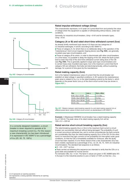
t (s)<br />
Im<br />
Fig. H35 : Category A circuit-breaker<br />
t (s )<br />
Im<br />
Fig. H36 : Category B circuit-breaker<br />
In a correctly <strong>design</strong>ed <strong>installation</strong>, a circuitbreaker<br />
is never required to operate at its<br />
maximum breaking current Icu. For this reason<br />
a new characteristic Ics has been introduced.<br />
It is expressed in IEC 60947-2 as a percentage<br />
<strong>of</strong> Icu (25, 50, 75, 100%)<br />
(1) O represents an opening operation.<br />
CO represents a closing operation followed by an opening<br />
operation.<br />
I<br />
Icw<br />
Icu<br />
I(A)<br />
I(A )<br />
4 Circuit-breaker<br />
Rated impulse-withstand voltage (Uimp)<br />
This characteristic expresses, in kV peak (<strong>of</strong> a prescribed form and polarity) the value<br />
<strong>of</strong> voltage which the equipment is capable <strong>of</strong> withstanding without failure, under test<br />
conditions.<br />
<strong>General</strong>ly, for industrial circuit-breakers, Uimp = 8 kV and for domestic types,<br />
Uimp = 6 kV.<br />
Category (A or B) and rated short-time withstand current (Icw)<br />
As already briefly mentioned (sub-clause 4.2) there are two categories <strong>of</strong><br />
LV industrial switchgear, A and B, according to IEC 60947-2:<br />
b Those <strong>of</strong> category A, for which there is no deliberate delay in the operation <strong>of</strong> the<br />
“instantaneous” short-circuit magnetic tripping device (see Fig. H35), are generally<br />
moulded-case type circuit-breakers, and<br />
b Those <strong>of</strong> category B for which, in order to discriminate with other circuit-breakers<br />
on a time basis, it is possible to delay the tripping <strong>of</strong> the CB, where the fault-current<br />
level is lower than that <strong>of</strong> the short-time withstand current rating (Icw) <strong>of</strong> the CB<br />
(see Fig. H36). This is generally applied to large open-type circuit-breakers and<br />
to certain heavy-duty moulded-case types. Icw is the maximum current that the B<br />
category CB can withstand, thermally and electrodynamically, without sustaining<br />
damage, for a period <strong>of</strong> time given by the manufacturer.<br />
Rated making capacity (Icm)<br />
Icm is the highest instantaneous value <strong>of</strong> current that the circuit-breaker can<br />
establish at rated voltage in specified conditions. In AC systems this instantaneous<br />
peak value is related to Icu (i.e. to the rated breaking current) by the factor k, which<br />
depends on the power factor (cos ϕ) <strong>of</strong> the short-circuit current loop (as shown in<br />
Figure H37 ).<br />
Schneider Electric - Electrical <strong>installation</strong> guide 2008<br />
Icu cos ϕ Icm = kIcu<br />
6 kA < Icu y 10 kA 0.5 1.7 x Icu<br />
10 kA < Icu y 20 kA 0.3 2 x Icu<br />
20 kA < Icu y 50 kA 0.25 2.1 x Icu<br />
50 kA y Icu 0.2 2.2 x Icu<br />
Fig. H37 : Relation between rated breaking capacity Icu and rated making capacity Icm at<br />
different power-factor values <strong>of</strong> short-circuit current, as standardized in IEC 60947-2<br />
Example: A Masterpact NW08H2 circuit-breaker has a rated breaking capacity<br />
Icu <strong>of</strong> 100 kA. The peak value <strong>of</strong> its rated making capacity Icm will be<br />
100 x 2.2 = 220 kA.<br />
Rated service short-circuit breaking capacity (Ics)<br />
The rated breaking capacity (Icu) or (Icn) is the maximum fault-current a circuitbreaker<br />
can successfully interrupt without being damaged. The probability <strong>of</strong> such<br />
a current occurring is extremely low, and in normal circumstances the fault-currents<br />
are considerably less than the rated breaking capacity (Icu) <strong>of</strong> the CB. On the other<br />
hand it is important that high currents (<strong>of</strong> low probability) be interrupted under good<br />
conditions, so that the CB is immediately available for reclosure, after the faulty<br />
circuit has been repaired. It is for these reasons that a new characteristic (Ics) has<br />
been created, expressed as a percentage <strong>of</strong> Icu, viz: 25, 50, 75, 100% for industrial<br />
circuit-breakers. The standard test sequence is as follows:<br />
b O - CO - CO (1) (at Ics)<br />
b Tests carried out following this sequence are intended to verify that the CB is in a<br />
good state and available for normal service<br />
For domestic CBs, Ics = k Icn. The factor k values are given in IEC 60898 table XIV.<br />
In Europe it is the industrial practice to use a k factor <strong>of</strong> 100% so that Ics = Icu.


