

Chapter A General rules of electrical installation design
Chapter A General rules of electrical installation design
Chapter A General rules of electrical installation design

Create successful ePaper yourself
Turn your PDF publications into a flip-book with our unique Google optimized e-Paper software.
M16<br />
© Schneider Electric - all rights reserved<br />
M - Harmonic management<br />
PowerLogic System with Power Meter and<br />
Circuit Monitor, Micrologic <strong>of</strong>fer a complete<br />
range <strong>of</strong> devices for the detection <strong>of</strong> harmonic<br />
distortion<br />
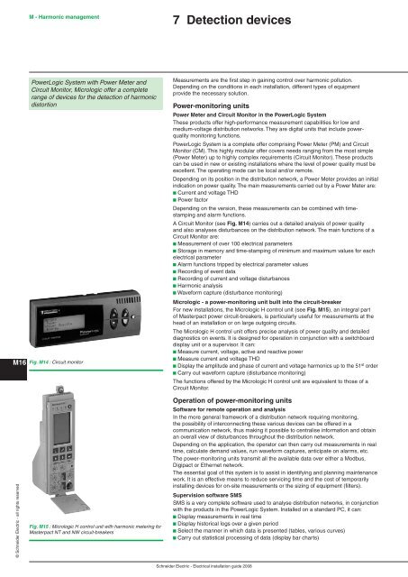
Fig. M14 : Circuit monitor<br />
Fig. M15 : Micrologic H control unit with harmonic metering for<br />
Masterpact NT and NW circuit-breakers<br />
7 Detection devices<br />
Measurements are the first step in gaining control over harmonic pollution.<br />
Depending on the conditions in each <strong>installation</strong>, different types <strong>of</strong> equipment<br />
provide the necessary solution.<br />
Power-monitoring units<br />
Power Meter and Circuit Monitor in the PowerLogic System<br />
These products <strong>of</strong>fer high-performance measurement capabilities for low and<br />
medium-voltage distribution networks. They are digital units that include powerquality<br />
monitoring functions.<br />
PowerLogic System is a complete <strong>of</strong>fer comprising Power Meter (PM) and Circuit<br />
Monitor (CM). This highly modular <strong>of</strong>fer covers needs ranging from the most simple<br />
(Power Meter) up to highly complex requirements (Circuit Monitor). These products<br />
can be used in new or existing <strong>installation</strong>s where the level <strong>of</strong> power quality must be<br />
excellent. The operating mode can be local and/or remote.<br />
Depending on its position in the distribution network, a Power Meter provides an initial<br />
indication on power quality. The main measurements carried out by a Power Meter are:<br />
b Current and voltage THD<br />
b Power factor<br />
Depending on the version, these measurements can be combined with timestamping<br />
and alarm functions.<br />
A Circuit Monitor (see Fig. M14) carries out a detailed analysis <strong>of</strong> power quality<br />
and also analyses disturbances on the distribution network. The main functions <strong>of</strong> a<br />
Circuit Monitor are:<br />
b Measurement <strong>of</strong> over 100 <strong>electrical</strong> parameters<br />
b Storage in memory and time-stamping <strong>of</strong> minimum and maximum values for each<br />
<strong>electrical</strong> parameter<br />
b Alarm functions tripped by <strong>electrical</strong> parameter values<br />
b Recording <strong>of</strong> event data<br />
b Recording <strong>of</strong> current and voltage disturbances<br />
b Harmonic analysis<br />
b Waveform capture (disturbance monitoring)<br />
Micrologic - a power-monitoring unit built into the circuit-breaker<br />
For new <strong>installation</strong>s, the Micrologic H control unit (see Fig. M15), an integral part<br />
<strong>of</strong> Masterpact power circuit-breakers, is particularly useful for measurements at the<br />
head <strong>of</strong> an <strong>installation</strong> or on large outgoing circuits.<br />
The Micrologic H control unit <strong>of</strong>fers precise analysis <strong>of</strong> power quality and detailed<br />
diagnostics on events. It is <strong>design</strong>ed for operation in conjunction with a switchboard<br />
display unit or a supervisor. It can:<br />
b Measure current, voltage, active and reactive power<br />
b Measure current and voltage THD<br />
b Display the amplitude and phase <strong>of</strong> current and voltage harmonics up to the 51 st order<br />
b Carry out waveform capture (disturbance monitoring)<br />
The functions <strong>of</strong>fered by the Micrologic H control unit are equivalent to those <strong>of</strong> a<br />
Circuit Monitor.<br />
Operation <strong>of</strong> power-monitoring units<br />
S<strong>of</strong>tware for remote operation and analysis<br />
In the more general framework <strong>of</strong> a distribution network requiring monitoring,<br />
the possibility <strong>of</strong> interconnecting these various devices can be <strong>of</strong>fered in a<br />
communication network, thus making it possible to centralise information and obtain<br />
an overall view <strong>of</strong> disturbances throughout the distribution network.<br />
Depending on the application, the operator can then carry out measurements in real<br />
time, calculate demand values, run waveform captures, anticipate on alarms, etc.<br />
The power-monitoring units transmit all the available data over either a Modbus,<br />
Digipact or Ethernet network.<br />
The essential goal <strong>of</strong> this system is to assist in identifying and planning maintenance<br />
work. It is an effective means to reduce servicing time and the cost <strong>of</strong> temporarily<br />
installing devices for on-site measurements or the sizing <strong>of</strong> equipment (filters).<br />
Supervision s<strong>of</strong>tware SMS<br />
SMS is a very complete s<strong>of</strong>tware used to analyse distribution networks, in conjunction<br />
with the products in the PowerLogic System. Installed on a standard PC, it can:<br />
b Display measurements in real time<br />
b Display historical logs over a given period<br />
b Select the manner in which data is presented (tables, various curves)<br />
b Carry out statistical processing <strong>of</strong> data (display bar charts)<br />
Schneider Electric - Electrical <strong>installation</strong> guide 2008


