

Chapter A General rules of electrical installation design
Chapter A General rules of electrical installation design
Chapter A General rules of electrical installation design

You also want an ePaper? Increase the reach of your titles
YUMPU automatically turns print PDFs into web optimized ePapers that Google loves.
L - Power factor correction and<br />
harmonic filtering<br />
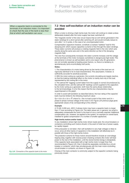
When a capacitor bank is connected to the<br />
terminals <strong>of</strong> an induction motor, it is important<br />
to check that the size <strong>of</strong> the bank is less than<br />
that at which self-excitation can occur<br />
Fig. L26 : Connection <strong>of</strong> the capacitor bank to the motor<br />
7 Power factor correction <strong>of</strong><br />
induction motors<br />
7.2 How self-excitation <strong>of</strong> an induction motor can be<br />
avoided<br />
When a motor is driving a high-inertia load, the motor will continue to rotate (unless<br />
deliberately braked) after the motor supply has been switched <strong>of</strong>f.<br />
The “magnetic inertia” <strong>of</strong> the rotor circuit means that an emf will be generated in the<br />
stator windings for a short period after switching <strong>of</strong>f, and would normally reduce to<br />
zero after 1 or 2 cycles, in the case <strong>of</strong> an uncompensated motor.<br />
Compensation capacitors however, constitute a 3-phase “wattless” load for this<br />
decaying emf, which causes capacitive currents to flow through the stator windings.<br />
These stator currents will produce a rotating magnetic field in the rotor which acts<br />
exactly along the same axis and in the same direction as that <strong>of</strong> the decaying<br />
magnetic field.<br />
The rotor flux consequently increases; the stator currents increase; and the voltage<br />
at the terminals <strong>of</strong> the motor increases; sometimes to dangerously-high levels. This<br />
phenomenon is known as self-excitation and is one reason why AC generators<br />
are not normally operated at leading power factors, i.e. there is a tendency to<br />
spontaneously (and uncontrollably) self excite.<br />
Notes:<br />
1. The characteristics <strong>of</strong> a motor being driven by the inertia <strong>of</strong> the load are not<br />
rigorously identical to its no-load characteristics. This assumption, however, is<br />
sufficiently accurate for practical purposes.<br />
2. With the motor acting as a generator, the currents circulating are largely reactive,<br />
so that the braking (retarding) effect on the motor is mainly due only to the load<br />
represented by the cooling fan in the motor.<br />
3. The (almost 90° lagging) current taken from the supply in normal circumstances by<br />
the unloaded motor, and the (almost 90° leading) current supplied to the capacitors<br />
by the motor acting as a generator, both have the same phase relationship<br />
to the terminalvoltage. It is for this reason that the two characteristics may be<br />
superimposed on the graph.<br />
In order to avoid self-excitation as described above, the kvar rating <strong>of</strong> the capacitor<br />
bank must be limited to the following maximum value:<br />
Qc y 0.9 x Io x Un x 3 where Io = the no-load current <strong>of</strong> the motor and Un =<br />
phase-to-phase nominal voltage <strong>of</strong> the motor in kV. Figure L24 previous page gives<br />
appropriate values <strong>of</strong> Qc corresponding to this criterion.<br />
Example<br />
A 75 kW, 3,000 rpm, 400 V, 3-phase motor may have a capacitor bank no larger<br />
than 17 kvar according to Figure L24. The table values are, in general, too small to<br />
adequately compensate the motor to the level <strong>of</strong> cos ϕ normally required. Additional<br />
compensation can, however, be applied to the system, for example an overall bank,<br />
installed for global compensation <strong>of</strong> a number <strong>of</strong> smaller appliances.<br />
High-inertia motors and/or loads<br />
In any <strong>installation</strong> where high-inertia motor driven loads exist, the circuit-breakers or<br />
contactors controlling such motors should, in the event <strong>of</strong> total loss <strong>of</strong> power supply,<br />
be rapidly tripped.<br />
If this precaution is not taken, then self excitation to very high voltages is likely to<br />
occur, since all other banks <strong>of</strong> capacitors in the <strong>installation</strong> will effectively be in<br />
parallel with those <strong>of</strong> the high-inertia motors.<br />
The protection scheme for these motors should therefore include an overvoltage<br />
tripping relay, together with reverse-power checking contacts (the motor will feed<br />
power to the rest <strong>of</strong> the <strong>installation</strong>, until the stored inertial energy is dissipated).<br />
If the capacitor bank associated with a high inertia motor is larger than that<br />
recommended in Figure L24, then it should be separately controlled by a circuitbreaker<br />
or contactor, which trips simultaneously with the main motor-controlling<br />
circuit-breaker or contactor, as shown in Figure L26.<br />
Closing <strong>of</strong> the main contactor is commonly subject to the capacitor contactor being<br />
previously closed.<br />
Schneider Electric - Electrical <strong>installation</strong> guide 2008<br />
L19<br />
© Schneider Electric - all rights reserved


