

Chapter A General rules of electrical installation design
Chapter A General rules of electrical installation design
Chapter A General rules of electrical installation design

Create successful ePaper yourself
Turn your PDF publications into a flip-book with our unique Google optimized e-Paper software.
H18<br />
© Schneider Electric - all rights reserved<br />
H - LV switchgear: functions & selection<br />
The choice <strong>of</strong> a range <strong>of</strong> circuit-breakers is<br />
determined by: the <strong>electrical</strong> characteristics <strong>of</strong><br />
the <strong>installation</strong>, the environment, the loads and<br />
a need for remote control, together with the type<br />
<strong>of</strong> telecommunications system envisaged<br />
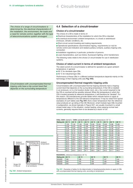
Circuit-breakers with uncompensated thermal<br />
tripping units have a trip current level that<br />
depends on the surrounding temperature<br />
Ambient<br />
temperature<br />
Single CB<br />
in free air<br />
Fig. H40 : Ambient temperature<br />
Temperature <strong>of</strong> air<br />
surrouding the<br />
circuit breakers<br />
Circuit breakers installed<br />
in an enclosure<br />
Ambient<br />
temperature<br />
4 Circuit-breaker<br />
4.4 Selection <strong>of</strong> a circuit-breaker<br />
Choice <strong>of</strong> a circuit-breaker<br />
The choice <strong>of</strong> a CB is made in terms <strong>of</strong>:<br />
b Electrical characteristics <strong>of</strong> the <strong>installation</strong> for which the CB is intended<br />
b Its eventual environment: ambient temperature, in a kiosk or switchboard<br />
enclosure, climatic conditions, etc.<br />
b Short-circuit current breaking and making requirements<br />
b Operational specifications: discriminative tripping, requirements (or not) for<br />
remote control and indication and related auxiliary contacts, auxiliary tripping coils,<br />
connection<br />
b Installation regulations; in particular: protection <strong>of</strong> persons<br />
b Load characteristics, such as motors, fluorescent lighting, LV/LV transformers<br />
The following notes relate to the choice LV circuit-breaker for use in distribution<br />
systems.<br />
Choice <strong>of</strong> rated current in terms <strong>of</strong> ambient temperature<br />
The rated current <strong>of</strong> a circuit-breaker is defined for operation at a given ambient<br />
temperature, in general:<br />
b 30 °C for domestic-type CBs<br />
b 40 °C for industrial-type CBs<br />
Performance <strong>of</strong> these CBs in a different ambient temperature depends mainly on the<br />
technology <strong>of</strong> their tripping units (see Fig. H40).<br />
Uncompensated thermal magnetic tripping units<br />
Circuit-breakers with uncompensated thermal tripping elements have a trippingcurrent<br />
level that depends on the surrounding temperature. If the CB is installed<br />
in an enclosure, or in a hot location (boiler room, etc.), the current required to trip<br />
the CB on overload will be sensibly reduced. When the temperature in which the<br />
CB is located exceeds its reference temperature, it will therefore be “derated”. For<br />
this reason, CB manufacturers provide tables which indicate factors to apply at<br />
temperatures different to the CB reference temperature. It may be noted from typical<br />
examples <strong>of</strong> such tables (see Fig. H41) that a lower temperature than the reference<br />
value produces an up-rating <strong>of</strong> the CB. Moreover, small modular-type CBs mounted<br />
in juxtaposition, as shown typically in Figure H27, are usually mounted in a small<br />
closed metal case. In this situation, mutual heating, when passing normal load<br />
currents, generally requires them to be derated by a factor <strong>of</strong> 0.8.<br />
C60a, C60H: curve C. C60N: curves B and C (reference temperature: 30 °C)<br />
Rating (A) 20 °C 25 °C 30 °C 35 °C 40 °C 45 °C 50 °C 55 °C 60 °C<br />
1 1.05 1.02 1.00 0.98 0.95 0.93 0.90 0.88 0.85<br />
2 2.08 2.04 2.00 1.96 1.92 1.88 1.84 1.80 1.74<br />
3 3.18 3.09 3.00 2.91 2.82 2.70 2.61 2.49 2.37<br />
4 4.24 4.12 4.00 3.88 3.76 3.64 3.52 3.36 3.24<br />
6 6.24 6.12 6.00 5.88 5.76 5.64 5.52 5.40 5.30<br />
10 10.6 10.3 10.0 9.70 9.30 9.00 8.60 8.20 7.80<br />
16 16.8 16.5 16.0 15.5 15.2 14.7 14.2 13.8 13.5<br />
20 21.0 20.6 20.0 19.4 19.0 18.4 17.8 17.4 16.8<br />
25 26.2 25.7 25.0 24.2 23.7 23.0 22.2 21.5 20.7<br />
32 33.5 32.9 32.0 31.4 30.4 29.8 28.4 28.2 27.5<br />
40 42.0 41.2 40.0 38.8 38.0 36.8 35.6 34.4 33.2<br />
50 52.5 51.5 50.0 48.5 47.4 45.5 44.0 42.5 40.5<br />
63 66.2 64.9 63.0 61.1 58.0 56.7 54.2 51.7 49.2<br />
NS250N/H/L (reference temperature: 40 °C)<br />
Rating (A) 40 °C 45 °C 50 °C 55 °C 60 °C<br />
TM160D 160 156 152 147 144<br />
TM200D 200 195 190 185 180<br />
TM250D 250 244 238 231 225<br />
Fig. H41 : Examples <strong>of</strong> tables for the determination <strong>of</strong> derating/uprating factors to apply to CBs<br />
with uncompensated thermal tripping units, according to temperature<br />
Schneider Electric - Electrical <strong>installation</strong> guide 2008


