

Chapter A General rules of electrical installation design
Chapter A General rules of electrical installation design
Chapter A General rules of electrical installation design

You also want an ePaper? Increase the reach of your titles
YUMPU automatically turns print PDFs into web optimized ePapers that Google loves.
G38<br />
© Schneider Electric - all rights reserved<br />
G - Sizing and protection <strong>of</strong> conductors<br />
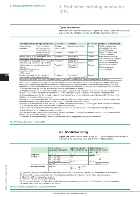
Fig. G57 : Choice <strong>of</strong> protective conductors (PE)<br />
Fig. G58 : Minimum cross section area <strong>of</strong> protective conductors<br />
Types <strong>of</strong> materials<br />
Materials <strong>of</strong> the kinds mentioned below in Figure G57 can be used for PE conductors,<br />
provided that the conditions mentioned in the last column are satisfied.<br />
Type <strong>of</strong> protective earthing conductor (PE) IT scheme TN scheme TT scheme Conditions to be respected<br />
Supplementary In the same cable Strongly Strongly recommended Correct The PE conductor must<br />
conductor as the phases, or in recommended be insulated to the same<br />
the same cable run level as the phases<br />
Independent <strong>of</strong> the Possible (1) Possible (1) (2) Correct b The PE conductor may<br />
phase conductors be bare or insulated (2)<br />
Metallic housing <strong>of</strong> bus-trunking or <strong>of</strong> other Possible (3) PE possible (3) Correct b The <strong>electrical</strong> continuity<br />
prefabricated prewired ducting (5) PEN possible (8) must be assured by protection<br />
External sheath <strong>of</strong> extruded, mineral- insulated Possible (3) PE possible (3) Possible against deterioration by<br />
conductors (e.g. «pyrotenax» type systems) PEN not recommended (2)(3) Certain extraneous conductive elements<br />
mechanical, chemical and<br />
(6) Possible (4) PE possible (4) Possible<br />
electrochemical hazards<br />
such as: PEN forbidden b Their conductance<br />
b Steel building structures<br />
b Machine frames<br />
b Water pipes<br />
must be adequate<br />
(7)<br />
Metallic cable ways, such as, conduits (9) , Possible (4) PE possible (4) Possible<br />
ducts, trunking, trays, ladders, and so on… PEN not recommended (2)(4)<br />
Forbidden for use as PE conductors, are: metal conduits (9) , gas pipes, hot-water pipes, cable-armouring tapes (9) or wires (9)<br />
(1) In TN and IT schemes, fault clearance is generally achieved by overcurrent devices (fuses or circuit-breakers) so that the impedance<br />
<strong>of</strong> the fault-current loop must be sufficiently low to assure positive protective device operation. The surest means <strong>of</strong> achieving a low loop<br />
impedance is to use a supplementary core in the same cable as the circuit conductors (or taking the same route as the circuit conductors).<br />
This solution minimizes the inductive reactance and therefore the impedance <strong>of</strong> the loop.<br />
(2) The PEN conductor is a neutral conductor that is also used as a protective earth conductor. This means that a current may be flowing<br />
through it at any time (in the absence <strong>of</strong> an earth fault). For this reason an insulated conductor is recommended for PEN operation.<br />
(3) The manufacturer provides the necessary values <strong>of</strong> R and X components <strong>of</strong> the impedances (phase/PE, phase/PEN) to include in the<br />
calculation <strong>of</strong> the earth-fault loop impedance.<br />
(4) Possible, but not recomended, since the impedance <strong>of</strong> the earth-fault loop cannot be known at the <strong>design</strong> stage. Measurements on the<br />
completed <strong>installation</strong> are the only practical means <strong>of</strong> assuring adequate protection for persons.<br />
(5) It must allow the connection <strong>of</strong> other PE conductors. Note: these elements must carry an indivual green/yellow striped visual indication,<br />
15 to 100 mm long (or the letters PE at less than 15 cm from each extremity).<br />
(6) These elements must be demountable only if other means have been provided to ensure uninterrupted continuity <strong>of</strong> protection.<br />
(7) With the agreement <strong>of</strong> the appropriate water authorities.<br />
(8) In the prefabricated pre-wired trunking and similar elements, the metallic housing may be used as a PEN conductor, in parallel with the<br />
corresponding bar, or other PE conductor in the housing.<br />
(9) Forbidden in some countries only. Universally allowed to be used for supplementary equipotential conductors.<br />
6.2 Conductor sizing<br />
Figure G58 below is based on IEC 60364-5-54. This table provides two methods <strong>of</strong><br />
determining the appropriate c.s.a. for both PE or PEN conductors.<br />
c.s.a. <strong>of</strong> phase Minimum c.s.a. <strong>of</strong> Minimum c.s.a. <strong>of</strong><br />
conductors Sph (mm2 ) PE conductor (mm2 ) PEN conductor (mm2 )<br />
Cu Al<br />
Simplified Sph y 16 S (2)<br />
ph Sph<br />
(3)<br />
Sph<br />
(3)<br />
method (1) 16 < Sph y 25 16 16<br />
25 < Sph y 35 25<br />
35 < Sph y 50 Sph /2 Sph /2<br />
Sph > 50 S Sph /2<br />
Adiabatic method Any size<br />
6 Protective earthing conductor<br />
(PE)<br />
SPE/PEN<br />
=<br />
(1) Data valid if the prospective conductor is <strong>of</strong> the same material as the line conductor. Otherwise, a correction factor must be applied.<br />
(2) When the PE conductor is separated from the circuit phase conductors, the following minimum values must be respected:<br />
b 2.5 mm 2 if the PE is mechanically protected<br />
b 4 mm 2 if the PE is not mechanically protected<br />
(3) For mechanical reasons, a PEN conductor, shall have a cross-sectional area not less than 10 mm 2 in copper or 16 mm 2 in aluminium.<br />
(4) Refer to table G53 for the application <strong>of</strong> this formula.<br />
I ⋅t<br />
k<br />
2<br />
(3) (4)<br />
(3) (4)<br />
Schneider Electric - Electrical <strong>installation</strong> guide 2008


