

Chapter A General rules of electrical installation design
Chapter A General rules of electrical installation design
Chapter A General rules of electrical installation design

You also want an ePaper? Increase the reach of your titles
YUMPU automatically turns print PDFs into web optimized ePapers that Google loves.
D - MV & LV architecture selection guide<br />
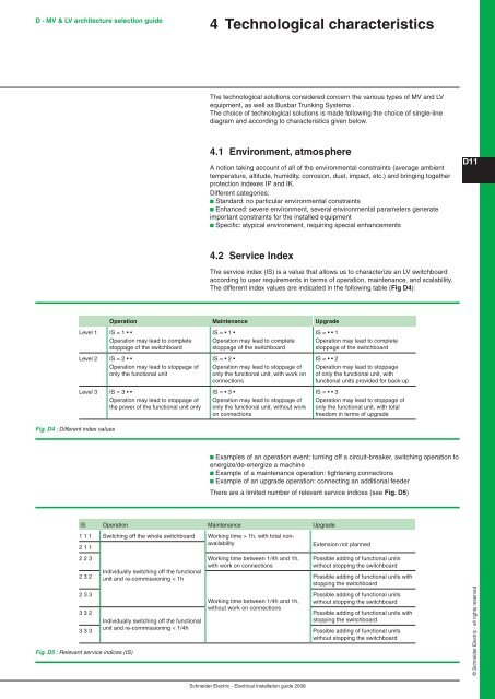
Fig. D4 : Different index values<br />
4 Technological characteristics<br />
The technological solutions considered concern the various types <strong>of</strong> MV and LV<br />
equipment, as well as Busbar Trunking Systems .<br />
The choice <strong>of</strong> technological solutions is made following the choice <strong>of</strong> single-line<br />
diagram and according to characteristics given below.<br />
4.1 Environment, atmosphere<br />
A notion taking account <strong>of</strong> all <strong>of</strong> the environmental constraints (average ambient<br />
temperature, altitude, humidity, corrosion, dust, impact, etc.) and bringing together<br />
protection indexes IP and IK.<br />
Different categories:<br />
b Standard: no particular environmental constraints<br />
b Enhanced: severe environment, several environmental parameters generate<br />
important constraints for the installed equipment<br />
b Specific: atypical environment, requiring special enhancements<br />
4.2 Service Index<br />
The service index (IS) is a value that allows us to characterize an LV switchboard<br />
according to user requirements in terms <strong>of</strong> operation, maintenance, and scalability.<br />
The different index values are indicated in the following table (Fig D4):<br />
Operation Maintenance Upgrade<br />
Level 1 IS = 1 • •<br />
Operation may lead to complete<br />
stoppage <strong>of</strong> the switchboard<br />
Level 2 IS = 2 • •<br />
Operation may lead to stoppage <strong>of</strong><br />
only the functional unit<br />
Level 3 IS = 3 • •<br />
Operation may lead to stoppage <strong>of</strong><br />
the power <strong>of</strong> the functional unit only<br />
IS = • 1 •<br />
Operation may lead to complete<br />
stoppage <strong>of</strong> the switchboard<br />
IS = • 2 •<br />
Operation may lead to stoppage <strong>of</strong><br />
only the functional unit, with work on<br />
connections<br />
IS = • 3 •<br />
Operation may lead to stoppage <strong>of</strong><br />
only the functional unit, without work<br />
on connections<br />
Schneider Electric - Electrical <strong>installation</strong> guide 2008<br />
IS = • • 1<br />
Operation may lead to complete<br />
stoppage <strong>of</strong> the switchboard<br />
IS = • • 2<br />
Operation may lead to stoppage<br />
<strong>of</strong> only the functional unit, with<br />
functional units provided for back-up<br />
IS = • • 3<br />
Operation may lead to stoppage <strong>of</strong><br />
only the functional unit, with total<br />
freedom in terms <strong>of</strong> upgrade<br />
b Examples <strong>of</strong> an operation event: turning <strong>of</strong>f a circuit-breaker, switching operation to<br />
energize/de-energize a machine<br />
b Example <strong>of</strong> a maintenance operation: tightening connections<br />
b Example <strong>of</strong> an upgrade operation: connecting an additional feeder<br />
There are a limited number <strong>of</strong> relevant service indices (see Fig. D5)<br />
IS Operation Maintenance Upgrade<br />
1 1 1 Switching <strong>of</strong>f the whole switchboard Working time > 1h, with total nonavailability<br />
Extension not planned<br />
2 1 1<br />
2 2 3 Working time between 1/4h and 1h,<br />
with work on connections<br />
2 3 2<br />
Individually switching <strong>of</strong>f the functional<br />
unit and re-commissioning < 1h<br />
Working time between 1/4h and 1h,<br />
without work on connections<br />
Possible adding <strong>of</strong> functional units<br />
without stopping the switchboard<br />
Possible adding <strong>of</strong> functional units with<br />
stopping the switchboard<br />
2 3 3 Possible adding <strong>of</strong> functional units<br />
without stopping the switchboard<br />
3 3 2<br />
Possible adding <strong>of</strong> functional units with<br />
stopping the switchboard<br />
3 3 3<br />
Individually switching <strong>of</strong>f the functional<br />
unit and re-commissioning < 1/4h<br />
Possible adding <strong>of</strong> functional units<br />
without stopping the switchboard<br />
Fig. D5 : Relevant service indices (IS)<br />
D11<br />
© Schneider Electric - all rights reserved


