

Chapter A General rules of electrical installation design
Chapter A General rules of electrical installation design
Chapter A General rules of electrical installation design

Create successful ePaper yourself
Turn your PDF publications into a flip-book with our unique Google optimized e-Paper software.
L16<br />
© Schneider Electric - all rights reserved<br />
L - Power factor correction and<br />
harmonic filtering<br />
Where metering is carried out at the MV side<br />
<strong>of</strong> a transformer, the reactive-energy losses in<br />
the transformer may need to be compensated<br />
(depending on the tariff)<br />
Perfect transformer<br />
Primary<br />
winding<br />
Secondary<br />
winding<br />
Fig. L19 : Transformer reactances per phase<br />
Leakage reactance<br />
Magnetizing<br />
reactance<br />
The reactive power absorbed by a transformer<br />
cannot be neglected, and can amount to (about)<br />
5% <strong>of</strong> the transformer rating when supplying<br />
its full load. Compensation can be provided by<br />
a bank <strong>of</strong> capacitors. In transformers, reactive<br />
power is absorbed by both shunt (magnetizing)<br />
and series (leakage flux) reactances. Complete<br />
compensation can be provided by a bank <strong>of</strong><br />
shunt-connected LV capacitors<br />
I sin<br />
'<br />
I sin<br />
'<br />
I<br />
E<br />
Source<br />
XL<br />
V<br />
Load<br />
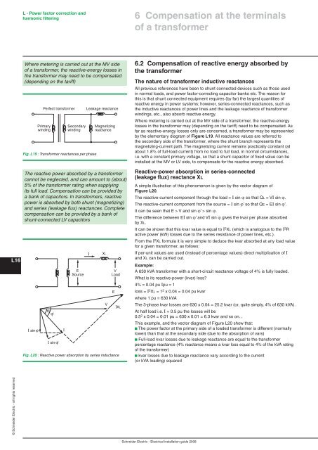
Fig. L20 : Reactive power absorption by series inductance<br />
I<br />
V<br />
E<br />
IXL<br />
6 Compensation at the terminals<br />
<strong>of</strong> a transformer<br />
6.2 Compensation <strong>of</strong> reactive energy absorbed by<br />
the transformer<br />
The nature <strong>of</strong> transformer inductive reactances<br />
All previous references have been to shunt connected devices such as those used<br />
in normal loads, and power factor-correcting capacitor banks etc. The reason for<br />
this is that shunt connected equipment requires (by far) the largest quantities <strong>of</strong><br />
reactive energy in power systems; however, series-connected reactances, such as<br />
the inductive reactances <strong>of</strong> power lines and the leakage reactance <strong>of</strong> transformer<br />
windings, etc., also absorb reactive energy.<br />
Where metering is carried out at the MV side <strong>of</strong> a transformer, the reactive-energy<br />
losses in the transformer may (depending on the tariff) need to be compensated. As<br />
far as reactive-energy losses only are concerned, a transformer may be represented<br />
by the elementary diagram <strong>of</strong> Figure L19. All reactance values are referred to<br />
the secondary side <strong>of</strong> the transformer, where the shunt branch represents the<br />
magnetizing-current path. The magnetizing current remains practically constant (at<br />
about 1.8% <strong>of</strong> full-load current) from no load to full load, in normal circumstances,<br />
i.e. with a constant primary voltage, so that a shunt capacitor <strong>of</strong> fixed value can be<br />
installed at the MV or LV side, to compensate for the reactive energy absorbed.<br />
Reactive-power absorption in series-connected<br />
(leakage flux) reactance XL<br />
A simple illustration <strong>of</strong> this phenomenon is given by the vector diagram <strong>of</strong><br />
Figure L20.<br />
The reactive-current component through the load = I sin ϕ so that QL = VI sin ϕ.<br />
The reactive-current component from the source = I sin ϕ’ so that QE = EI sin ϕ’.<br />
It can be seen that E > V and sin ϕ’ > sin ϕ.<br />
The difference between EI sin ϕ’ and VI sin ϕ gives the kvar per phase absorbed<br />
by XL.<br />
It can be shown that this kvar value is equal to I2XL (which is analogous to the I2R active power (kW) losses due to the series resistance <strong>of</strong> power lines, etc.).<br />
From the I2XL formula it is very simple to deduce the kvar absorbed at any load value<br />
for a given transformer, as follows:<br />
If per-unit values are used (instead <strong>of</strong> percentage values) direct multiplication <strong>of</strong> I<br />
and XL can be carried out.<br />
Example:<br />
A 630 kVA transformer with a short-circuit reactance voltage <strong>of</strong> 4% is fully loaded.<br />
What is its reactive-power (kvar) loss?<br />
4% = 0.04 pu Ipu = 1<br />
loss = I 2 XL = 1 2 x 0.04 = 0.04 pu kvar<br />
where 1 pu = 630 kVA<br />
The 3-phase kvar losses are 630 x 0.04 = 25.2 kvar (or, quite simply, 4% <strong>of</strong> 630 kVA).<br />
At half load i.e. I = 0.5 pu the losses will be<br />
0.5 2 x 0.04 = 0.01 pu = 630 x 0.01 = 6.3 kvar and so on...<br />
This example, and the vector diagram <strong>of</strong> Figure L20 show that:<br />
b The power factor at the primary side <strong>of</strong> a loaded transformer is different (normally<br />
lower) than that at the secondary side (due to the absorption <strong>of</strong> vars)<br />
b Full-load kvar losses due to leakage reactance are equal to the transformer<br />
percentage reactance (4% reactance means a kvar loss equal to 4% <strong>of</strong> the kVA rating<br />
<strong>of</strong> the transformer)<br />
b kvar losses due to leakage reactance vary according to the current<br />
(or kVA loading) squared<br />
Schneider Electric - Electrical <strong>installation</strong> guide 2008


