

Chapter A General rules of electrical installation design
Chapter A General rules of electrical installation design
Chapter A General rules of electrical installation design

You also want an ePaper? Increase the reach of your titles
YUMPU automatically turns print PDFs into web optimized ePapers that Google loves.
H - LV switchgear: functions & selection<br />
250 kVA<br />
20 kV/400 V<br />
Compact<br />
NS400N<br />
Fig. H44 : Example <strong>of</strong> a transformer in a consumer’s substation<br />
A1<br />
B1<br />
MV<br />
LV<br />
Tr1<br />
CBM<br />
CBP<br />
A2<br />
B2<br />
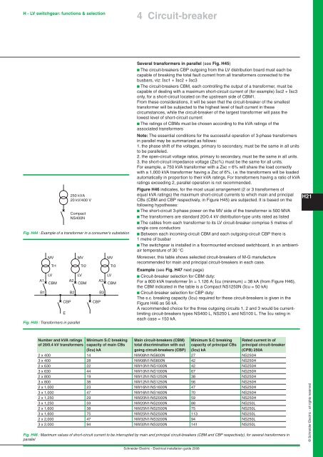
Fig. H45 : Transformers in parallel<br />
E<br />
MV<br />
LV<br />
Tr2<br />
CBM<br />
CBP<br />
A3<br />
B3<br />
MV<br />
LV<br />
Tr3<br />
CBM<br />
4 Circuit-breaker<br />
Several transformers in parallel (see Fig. H45)<br />
b The circuit-breakers CBP outgoing from the LV distribution board must each be<br />
capable <strong>of</strong> breaking the total fault current from all transformers connected to the<br />
busbars, viz: Isc1 + Isc2 + Isc3<br />
b The circuit-breakers CBM, each controlling the output <strong>of</strong> a transformer, must be<br />
capable <strong>of</strong> dealing with a maximum short-circuit current <strong>of</strong> (for example) Isc2 + Isc3<br />
only, for a short-circuit located on the upstream side <strong>of</strong> CBM1.<br />
From these considerations, it will be seen that the circuit-breaker <strong>of</strong> the smallest<br />
transformer will be subjected to the highest level <strong>of</strong> fault current in these<br />
circumstances, while the circuit-breaker <strong>of</strong> the largest transformer will pass the<br />
lowest level <strong>of</strong> short-circuit current<br />
b The ratings <strong>of</strong> CBMs must be chosen according to the kVA ratings <strong>of</strong> the<br />
associated transformers<br />
Note: The essential conditions for the successful operation <strong>of</strong> 3-phase transformers<br />
in parallel may be summarized as follows:<br />
1. the phase shift <strong>of</strong> the voltages, primary to secondary, must be the same in all units<br />
to be paralleled.<br />
2. the open-circuit voltage ratios, primary to secondary, must be the same in all units.<br />
3. the short-circuit impedance voltage (Zsc%) must be the same for all units.<br />
For example, a 750 kVA transformer with a Zsc = 6% will share the load correctly<br />
with a 1,000 kVA transformer having a Zsc <strong>of</strong> 6%, i.e. the transformers will be loaded<br />
automatically in proportion to their kVA ratings. For transformers having a ratio <strong>of</strong> kVA<br />
ratings exceeding 2, parallel operation is not recommended.<br />
Figure H46 indicates, for the most usual arrangement (2 or 3 transformers <strong>of</strong><br />
equal kVA ratings) the maximum short-circuit currents to which main and principal<br />
CBs (CBM and CBP respectively, in Figure H45) are subjected. It is based on the<br />
following hypotheses:<br />
b The short-circuit 3-phase power on the MV side <strong>of</strong> the transformer is 500 MVA<br />
b The transformers are standard 20/0.4 kV distribution-type units rated as listed<br />
b The cables from each transformer to its LV circuit-breaker comprise 5 metres <strong>of</strong><br />
single core conductors<br />
b Between each incoming-circuit CBM and each outgoing-circuit CBP there is<br />
1 metre <strong>of</strong> busbar<br />
b The switchgear is installed in a floormounted enclosed switchboard, in an ambientair<br />
temperature <strong>of</strong> 30 °C<br />
Moreover, this table shows selected circuit-breakers <strong>of</strong> M-G manufacture<br />
recommended for main and principal circuit-breakers in each case.<br />
Example (see Fig. H47 next page)<br />
b Circuit-breaker selection for CBM duty:<br />
For a 800 kVA transformer In = 1.126 A; Icu (minimum) = 38 kA (from Figure H46),<br />
the CBM indicated in the table is a Compact NS1250N (Icu = 50 kA)<br />
b Circuit-breaker selection for CBP duty:<br />
The s.c. breaking capacity (Icu) required for these circuit-breakers is given in the<br />
Figure H46 as 56 kA.<br />
A recommended choice for the three outgoing circuits 1, 2 and 3 would be currentlimiting<br />
circuit-breakers types NS400 L, NS250 L and NS100 L. The Icu rating in<br />
each case = 150 kA.<br />
Number and kVA ratings Minimum S.C breaking Main circuit-breakers (CBM) Minimum S.C breaking Rated current In <strong>of</strong><br />
<strong>of</strong> 20/0.4 kV transformers capacity <strong>of</strong> main CBs total discrimination with out capacity <strong>of</strong> principal CBs principal circuit-breaker<br />
(Icu) kA going circuit-breakers (CBP) (Icu) kA (CPB) 250A<br />
2 x 400 14 NW08N1/NS800N 27 NS250H<br />
3 x 400 28 NW08N1/NS800N 42 NS250H<br />
2 x 630 22 NW10N1/NS1000N 42 NS250H<br />
3 x 630 44 NW10N1/NS1000N 67 NS250H<br />
2 x 800 19 NW12N1/NS1250N 38 NS250H<br />
3 x 800 38 NW12N1/NS1250N 56 NS250H<br />
2 x 1,000 23 NW16N1/NS1600N 47 NS250H<br />
3 x 1,000 47 NW16N1/NS1600N 70 NS250H<br />
2 x 1,250 29 NW20N1/NS2000N 59 NS250H<br />
3 x 1,250 59 NW20N1/NS2000N 88 NS250L<br />
2 x 1,600 38 NW25N1/NS2500N 75 NS250L<br />
3 x 1,600 75 NW25N1/NS2500N 113 NS250L<br />
2 x 2,000 47 NW32N1/NS3200N 94 NS250L<br />
3 x 2,000 94 NW32N1/NS3200N 141 NS250L<br />
Fig. H46 : Maximum values <strong>of</strong> short-circuit current to be interrupted by main and principal circuit-breakers (CBM and CBP respectively), for several transformers in<br />
parallel<br />
Schneider Electric - Electrical <strong>installation</strong> guide 2008<br />
H21<br />
© Schneider Electric - all rights reserved


