

Chapter A General rules of electrical installation design
Chapter A General rules of electrical installation design
Chapter A General rules of electrical installation design

Create successful ePaper yourself
Turn your PDF publications into a flip-book with our unique Google optimized e-Paper software.
© Schneider Electric - all rights reserved<br />
B4<br />
B - Connection to the MV public<br />
distribution network<br />
The national standards <strong>of</strong> any particular country<br />
are normally rationalized to include one or two<br />
levels only <strong>of</strong> voltage, current, and fault-levels,<br />
etc.<br />
A circuit-breaker (or fuse switch, over a limited<br />
voltage range) is the only form <strong>of</strong> switchgear<br />
capable <strong>of</strong> safely breaking all kinds <strong>of</strong> fault<br />
currents occurring on a power system.<br />
I p<br />
Current (I)<br />
22I'' k<br />
t min<br />
22I b<br />
IDC 22Ik Time (t)<br />
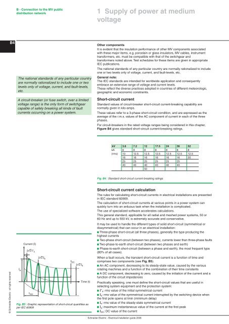
Fig. B5 : Graphic representation <strong>of</strong> short-circuit quantities as<br />
per IEC 60909<br />
Supply <strong>of</strong> power at medium<br />
voltage<br />
Other components<br />
It is evident that the insulation performance <strong>of</strong> other MV components associated<br />
with these major items, e.g. porcelain or glass insulators, MV cables, instrument<br />
transformers, etc. must be compatible with that <strong>of</strong> the switchgear and<br />
transformers noted above. Test schedules for these items are given in appropriate<br />
IEC publications.<br />
The national standards <strong>of</strong> any particular country are normally rationalized to include<br />
one or two levels only <strong>of</strong> voltage, current, and fault-levels, etc.<br />
<strong>General</strong> note:<br />
The IEC standards are intended for worldwide application and consequently<br />
embrace an extensive range <strong>of</strong> voltage and current levels.<br />
These reflect the diverse practices adopted in countries <strong>of</strong> different meteorologic,<br />
geographic and economic constraints.<br />
Short-circuit current<br />
Standard values <strong>of</strong> circuit-breaker short-circuit current-breaking capability are<br />
normally given in kilo-amps.<br />
These values refer to a 3-phase short-circuit condition, and are expressed as the<br />
average <strong>of</strong> the r.m.s. values <strong>of</strong> the AC component <strong>of</strong> current in each <strong>of</strong> the three<br />
phases.<br />
For circuit-breakers in the rated voltage ranges being considered in this chapter,<br />
Figure B4 gives standard short-circuit current-breaking ratings.<br />
kV 3.6 7.2 2 7.5 24 36 52<br />
kA 8 8 8 8 8 8 8<br />
(rms) 10 12.5 12.5 12.5 12.5 12.5 12.5<br />
16 16 16 16 16 16 20<br />
25 25 25 25 25 25<br />
40 40 40 40 40 40<br />
50<br />
Fig. B4 : Standard short-circuit current-breaking ratings<br />
Short-circuit current calculation<br />
The <strong>rules</strong> for calculating short-circuit currents in <strong>electrical</strong> <strong>installation</strong>s are presented<br />
in IEC standard 60909.<br />
The calculation <strong>of</strong> short-circuit currents at various points in a power system can<br />
quickly turn into an arduous task when the <strong>installation</strong> is complicated.<br />
The use <strong>of</strong> specialized s<strong>of</strong>tware accelerates calculations.<br />
This general standard, applicable for all radial and meshed power systems, 50 or<br />
60 Hz and up to 550 kV, is extremely accurate and conservative.<br />
It may be used to handle the different types <strong>of</strong> solid short-circuit (symmetrical or<br />
dissymmetrical) that can occur in an <strong>electrical</strong> <strong>installation</strong>:<br />
b Three-phase short-circuit (all three phases), generally the type producing the<br />
highest currents<br />
b Two-phase short-circuit (between two phases), currents lower than three-phase faults<br />
b Two-phase-to-earth short-circuit (between two phases and earth)<br />
b Phase-to-earth short-circuit (between a phase and earth), the most frequent type<br />
(80% <strong>of</strong> all cases).<br />
When a fault occurs, the transient short-circuit current is a function <strong>of</strong> time and<br />
comprises two components (see Fig. B5).<br />
b An AC component, decreasing to its steady-state value, caused by the various<br />
rotating machines and a function <strong>of</strong> the combination <strong>of</strong> their time constants<br />
b A DC component, decreasing to zero, caused by the initiation <strong>of</strong> the current and a<br />
function <strong>of</strong> the circuit impedances<br />
Practically speaking, one must define the short-circuit values that are useful in<br />
selecting system equipment and the protection system:<br />
b I’’ k: rms value <strong>of</strong> the initial symmetrical current<br />
b Ib: rms value <strong>of</strong> the symmetrical current interrupted by the switching device when<br />
the first pole opens at tmin (minimum delay)<br />
b Ik: rms value <strong>of</strong> the steady-state symmetrical current<br />
b Ip: maximum instantaneous value <strong>of</strong> the current at the first peak<br />
b IDC: DC value <strong>of</strong> the current<br />
Schneider Electric - Electrical <strong>installation</strong> guide 2008


