

Chapter A General rules of electrical installation design
Chapter A General rules of electrical installation design
Chapter A General rules of electrical installation design

You also want an ePaper? Increase the reach of your titles
YUMPU automatically turns print PDFs into web optimized ePapers that Google loves.
B18<br />
© Schneider Electric - all rights reserved<br />
B - Connection to the MV public<br />
distribution network<br />
Fig. B15 : Transformer with conservator tank<br />
Fig. B16 : Totally filled transformer<br />
1<br />
2<br />
3<br />
Overcurrent relay<br />
E/F relay<br />
HV LV<br />
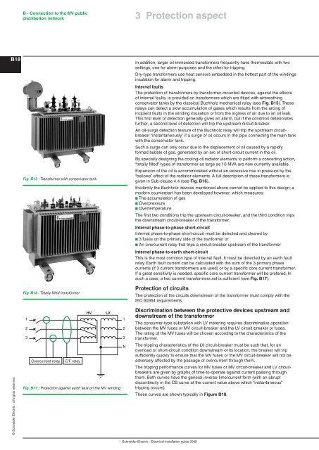
Fig. B17 : Protection against earth fault on the MV winding<br />
1<br />
2<br />
3<br />
N<br />
3 Protection aspect<br />
In addition, larger oil-immersed transformers frequently have thermostats with two<br />
settings, one for alarm purposes and the other for tripping.<br />
Dry-type transformers use heat sensors embedded in the hottest part <strong>of</strong> the windings<br />
insulation for alarm and tripping.<br />
Internal faults<br />
The protection <strong>of</strong> transformers by transformer-mounted devices, against the effects<br />
<strong>of</strong> internal faults, is provided on transformers which are fitted with airbreathing<br />
conservator tanks by the classical Buchholz mechanical relay (see Fig. B15). These<br />
relays can detect a slow accumulation <strong>of</strong> gases which results from the arcing <strong>of</strong><br />
incipient faults in the winding insulation or from the ingress <strong>of</strong> air due to an oil leak.<br />
This first level <strong>of</strong> detection generally gives an alarm, but if the condition deteriorates<br />
further, a second level <strong>of</strong> detection will trip the upstream circuit-breaker.<br />
An oil-surge detection feature <strong>of</strong> the Buchholz relay will trip the upstream circuitbreaker<br />
“instantaneously” if a surge <strong>of</strong> oil occurs in the pipe connecting the main tank<br />
with the conservator tank.<br />
Such a surge can only occur due to the displacement <strong>of</strong> oil caused by a rapidly<br />
formed bubble <strong>of</strong> gas, generated by an arc <strong>of</strong> short-circuit current in the oil.<br />
By specially <strong>design</strong>ing the cooling-oil radiator elements to perform a concerting action,<br />
“totally filled” types <strong>of</strong> transformer as large as 10 MVA are now currently available.<br />
Expansion <strong>of</strong> the oil is accommodated without an excessive rise in pressure by the<br />
“bellows” effect <strong>of</strong> the radiator elements. A full description <strong>of</strong> these transformers is<br />
given in Sub-clause 4.4 (see Fig. B16).<br />
Evidently the Buchholz devices mentioned above cannot be applied to this <strong>design</strong>; a<br />
modern counterpart has been developed however, which measures:<br />
b The accumulation <strong>of</strong> gas<br />
b Overpressure<br />
b Overtemperature<br />
The first two conditions trip the upstream circuit-breaker, and the third condition trips<br />
the downstream circuit-breaker <strong>of</strong> the transformer.<br />
Internal phase-to-phase short-circuit<br />
Internal phase-to-phase short-circuit must be detected and cleared by:<br />
b 3 fuses on the primary side <strong>of</strong> the tranformer or<br />
b An overcurrent relay that trips a circuit-breaker upstream <strong>of</strong> the transformer<br />
Internal phase-to-earth short-circuit<br />
This is the most common type <strong>of</strong> internal fault. It must be detected by an earth fault<br />
relay. Earth fault current can be calculated with the sum <strong>of</strong> the 3 primary phase<br />
currents (if 3 current transformers are used) or by a specific core current transformer.<br />
If a great sensitivity is needed, specific core current transformer will be prefered. In<br />
such a case, a two current transformers set is sufficient (see Fig. B17).<br />
Protection <strong>of</strong> circuits<br />
The protection <strong>of</strong> the circuits downstream <strong>of</strong> the transformer must comply with the<br />
IEC 60364 requirements.<br />
Discrimination between the protective devices upstream and<br />
downstream <strong>of</strong> the transformer<br />
The consumer-type substation with LV metering requires discriminative operation<br />
between the MV fuses or MV circuit-breaker and the LV circuit-breaker or fuses.<br />
The rating <strong>of</strong> the MV fuses will be chosen according to the characteristics <strong>of</strong> the<br />
transformer.<br />
The tripping characteristics <strong>of</strong> the LV circuit-breaker must be such that, for an<br />
overload or short-circuit condition downstream <strong>of</strong> its location, the breaker will trip<br />
sufficiently quickly to ensure that the MV fuses or the MV circuit-breaker will not be<br />
adversely affected by the passage <strong>of</strong> overcurrent through them.<br />
The tripping performance curves for MV fuses or MV circuit-breaker and LV circuitbreakers<br />
are given by graphs <strong>of</strong> time-to-operate against current passing through<br />
them. Both curves have the general inverse-time/current form (with an abrupt<br />
discontinuity in the CB curve at the current value above which “instantaneous”<br />
tripping occurs).<br />
These curves are shown typically in Figure B18.<br />
Schneider Electric - Electrical <strong>installation</strong> guide 2008


