


Create successful ePaper yourself
Turn your PDF publications into a flip-book with our unique Google optimized e-Paper software.
Philips Semiconductors Preliminary <strong>User</strong> <strong>Manual</strong><br />
ARM-based Microcontroller<br />
10. UART1<br />
FEATURES<br />
<strong>LPC2131</strong>/<strong>2132</strong>/<strong>2138</strong><br />
UART1 is identical to UART0, with the addition of a modem interface.<br />
16 byte Receive and Transmit FIFOs.<br />
Register locations conform to ‘550 industry standard.<br />
Receiver FIFO trigger points at 1, 4, 8, and 14 bytes.<br />
Built-in baud rate generator.<br />
Standard modem interface signals included (LPC<strong>2138</strong> only).<br />
<strong>LPC2131</strong>/<strong>2132</strong>/<strong>2138</strong> UART1 contains mechanism that enables implementation of either software or hardware flow control.<br />
PIN DESCRIPTION<br />
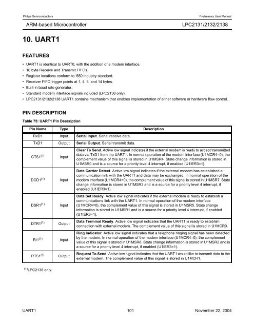
Table 75: UART1 Pin Description<br />
Pin Name Type Description<br />
RxD1 Input Serial Input. Serial receive data.<br />
TxD1 Output Serial Output. Serial transmit data.<br />
CTS1 (1)<br />
DCD1 (1)<br />
Input<br />
Input<br />
DSR1 (1) Input<br />
DTR1 (1) Output<br />
RI1 (1) Input<br />
RTS1 (1) Output<br />
(1) LPC<strong>2138</strong> only.<br />
Clear To Send. Active low signal indicates if the external modem is ready to accept transmitted<br />
data via TxD1 from the UART1. In normal operation of the modem interface (U1MCR4=0), the<br />
complement value of this signal is stored in U1MSR4. State change information is stored in<br />
U1MSR0 and is a source for a priority level 4 interrupt, if enabled (U1IER3=1).<br />
Data Carrier Detect. Active low signal indicates if the external modem has established a<br />
communication link with the UART1 and data may be exchanged. In normal operation of the<br />
modem interface (U1MCR4=0), the complement value of this signal is stored in U1MSR7. State<br />
change information is stored in U1MSR3 and is a source for a priority level 4 interrupt, if<br />
enabled (U1IER3=1).<br />
Data Set Ready. Active low signal indicates if the external modem is ready to establish a<br />
communications link with the UART1. In normal operation of the modem interface<br />
(U1MCR4=0), the complement value of this signal is stored in U1MSR5. State change<br />
information is stored in U1MSR1 and is a source for a priority level 4 interrupt, if enabled<br />
(U1IER3=1).<br />
Data Terminal Ready. Active low signal indicates that the UART1 is ready to establish<br />
connection with external modem. The complement value of this signal is stored in U1MCR0.<br />
Ring Indicator. Active low signal indicates that a telephone ringing signal has been detected<br />
by the modem. In normal operation of the modem interface (U1MCR4=0), the complement<br />
value of this signal is stored in U1MSR6. State change information is stored in U1MSR2 and is<br />
a source for a priority level 4 interrupt, if enabled (U1IER3=1).<br />
Request To Send. Active low signal indicates that the UART1 would like to transmit data to the<br />
external modem. The complement value of this signal is stored in U1MCR1.<br />
UART1 101 November 22, 2004


